Image projection apparatus and image display system
a technology of image projection and image display, which is applied in the field of image projection apparatus, can solve the problems of reducing the contrast of projected images, glare to users, and large heat generation of source lamps, and achieve the effect of reducing the air flow rate and reducing the intensity of the
- Summary
- Abstract
- Description
- Claims
- Application Information
AI Technical Summary
Benefits of technology
Problems solved by technology
Method used
Image

Examples
embodiment 1
(Overall Configuration of Projector)
[0027]FIG. 5 shows the configuration of a liquid crystal projector (image projection apparatus) that is a first embodiment (Embodiment 1) of the present invention.
[0028]In this figure, reference numeral 1 denotes a light source lamp (hereinafter referred to simply as “lamp”), which is an ultra high-pressure mercury discharge lamp in this embodiment. However, discharge lamps other than the ultra high-pressure mercury discharge lamp may be used as the lamp 1, such as a halogen lamp, a xenon lamp, and a metal halide lamp.
[0029]Reference numeral 2 denotes a lamp holder which holds the lamp 1, 3 an explosion-proof glass, and 4 a glass holder. Reference symbol α denotes an illumination optical system which converts light from the lamp 1 into collimated light with a uniform luminance distribution. Reference symbol β denotes a color separating / combining optical system. The color separating / combining optical system β separates the light from the illuminati...
embodiment 2
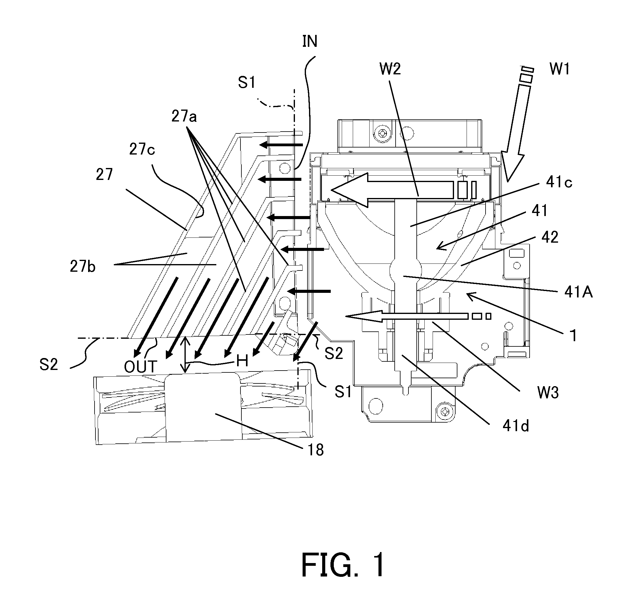
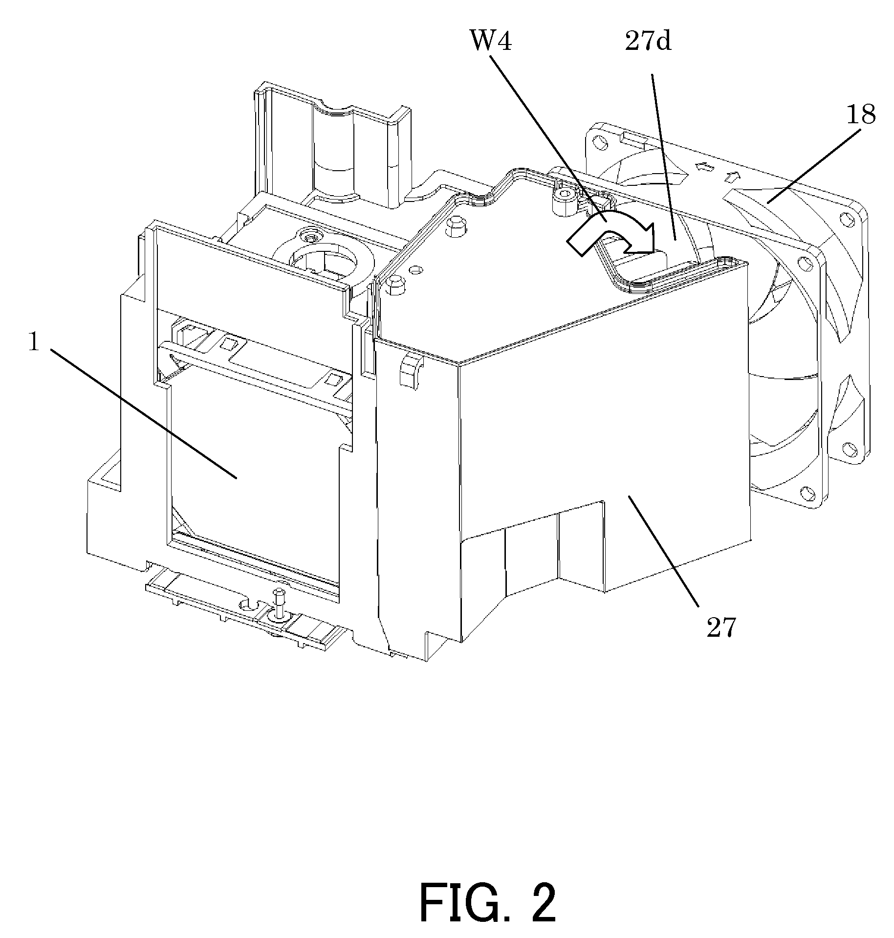
[0115]FIG. 3 shows the cooling structure in the vicinity of the lamp 1 and the exhaust fan 18 in a liquid crystal projector that is a second embodiment (Embodiment 2) of the present invention. Constituent elements identical to or having similar functions to those in Embodiment 1 are designated by the same reference numerals as those in Embodiment 1.
[0116]The flow of the air W2 flowing inside the reflector 42 to cool the light emitting portion 41A and the like (hereinafter referred to as “airflow W2” in this embodiment) is formed of the combination of an airflow which is blown from the lamp cooling fan 14 disposed at an upstream side from the lamp 1 and an airflow which is sucked into the exhaust fan 18. In contrast, the flow of the air W3 for cooling the neck portion (hereinafter referred to as “airflow W3” in this embodiment) is an airflow which is sucked into the exhaust fan 18.
[0117]Therefore, the flow volume of the airflow W2 is larger than that of the airflow W3. This flow volu...
embodiment 3
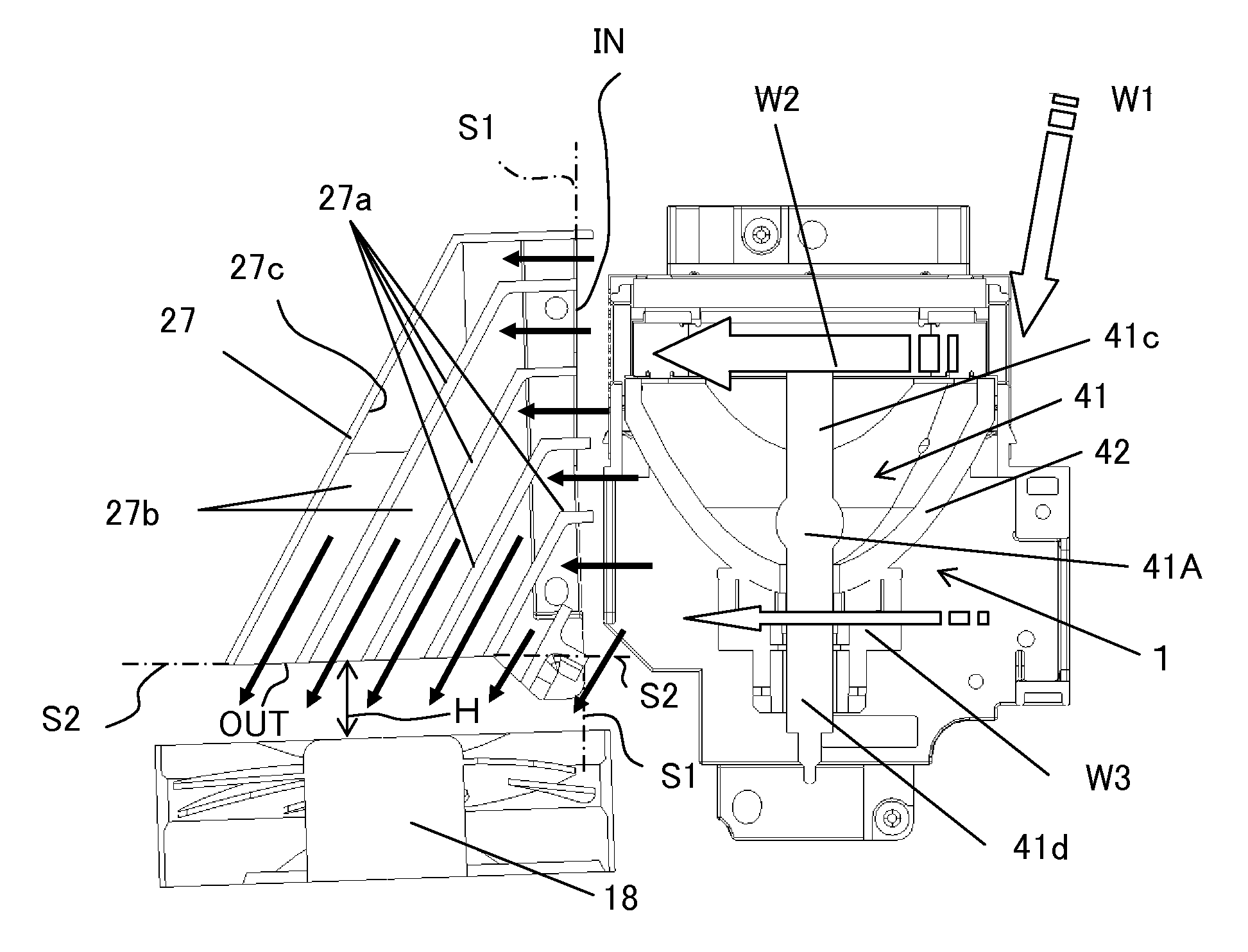
[0122]FIG. 4 shows the cooling structure in the vicinity of the lamp 1 and the exhaust fan 18 in a liquid crystal projector that is a third embodiment (Embodiment 3) of the present invention. Constituent elements identical to or having similar functions to those in Embodiment 1 are designated by the same reference numerals as those in Embodiment 1.
[0123]Leakage light from the lamp 1 in the liquid crystal projector gives a user an unpleasant feeling. Further, the leakage light illuminating the projection surface lowers the contrast of projected images. Therefore, in this embodiment, each air guiding wall 27a provided inside the exhaust duct 27 is configured such that a portion closer to the inflow opening IN than the outflow opening OUT is formed as a wall portion 27a3 extending toward an opposite side to the outflow opening OUT. In FIG. 4, since the outflow opening OUT is located on the lower side relative to the inflow opening IN, the wall portion 27a3 extends upward relative to th...
PUM
 Abstract
Description
Claims
Application Information
 - R&D
- Intellectual Property
- Life Sciences
- Materials
- Tech Scout
- Unparalleled Data Quality
- Higher Quality Content
- 60% Fewer Hallucinations
Browse by: Latest US Patents, China's latest patents, Technical Efficacy Thesaurus, Application Domain, Technology Topic, Popular Technical Reports.
© 2025 PatSnap. All rights reserved.Legal|Privacy policy|Modern Slavery Act Transparency Statement|Sitemap|About US| Contact US: help@patsnap.com