A u-tube superheater

A U-shaped tube and superheater technology, applied in the field of boiler component structure, can solve problems such as maintenance, overall replacement difficulty, uneven flow, difficult manufacturing, etc., to prolong continuous operation time, reduce uneven flow, and reduce uneven heating average effect

Active Publication Date: 2018-08-14
温州伟明环保能源有限公司
View PDF9 Cites 0 Cited by
  • Summary
  • Abstract
  • Description
  • Claims
  • Application Information

AI Technical Summary

Problems solved by technology

However, the pouring of refractory materials and the suspension installation of serpentine pipes are very inconvenient
In addition, the serpentine tube row also has uneven heating and uneven flow, which can easily lead to oxidation corrosion and pipe burst of the serpentine tube
[0004] Image 6 The tube-row superheater is displayed, but for the tube-row superheater, the structure of the superheater is complicated, it is difficult to manufacture, and it is difficult to maintain and replace it as a whole
In addition, there are many welding joints between the lower header and the pipe row, and the leakage of the pipe mouth often occurs during operation.

Method used


Image

  • A u-tube superheater
  • A u-tube superheater
  • A u-tube superheater

Examples


Embodiment 1

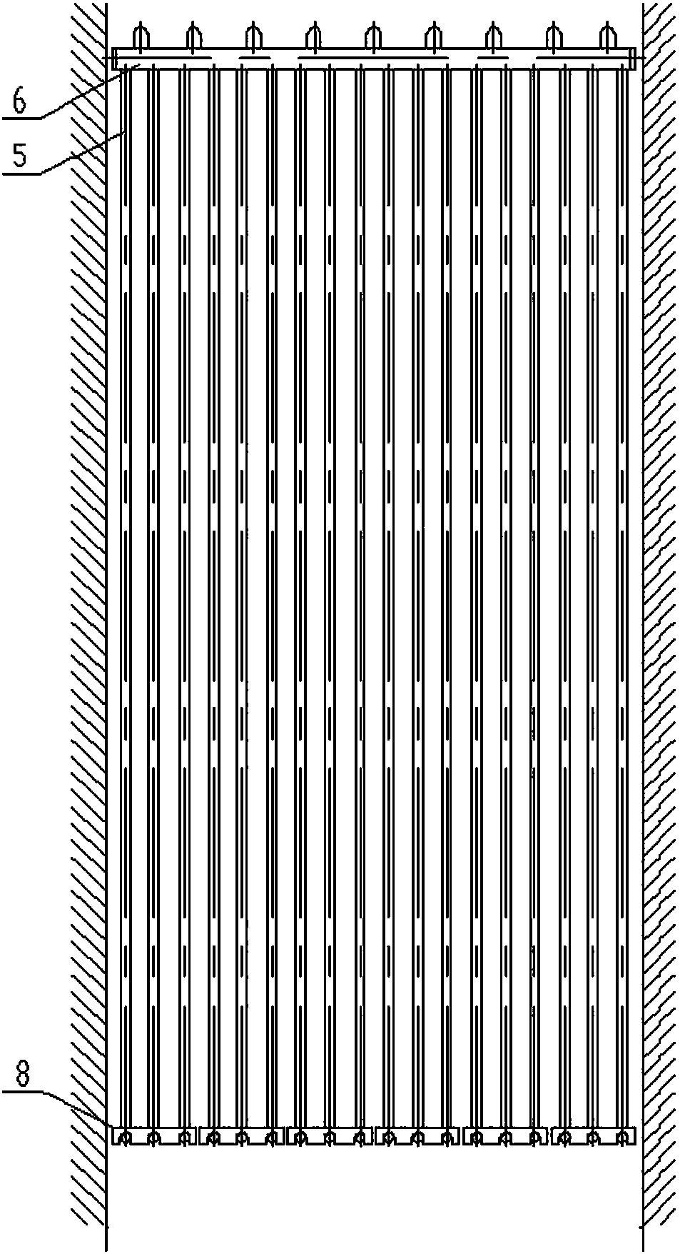
[0035] A U-shaped tube superheater is arranged in a horizontal flue. The U-shaped tube superheater of this embodiment adopts a single-tube coil U-shaped tube type.

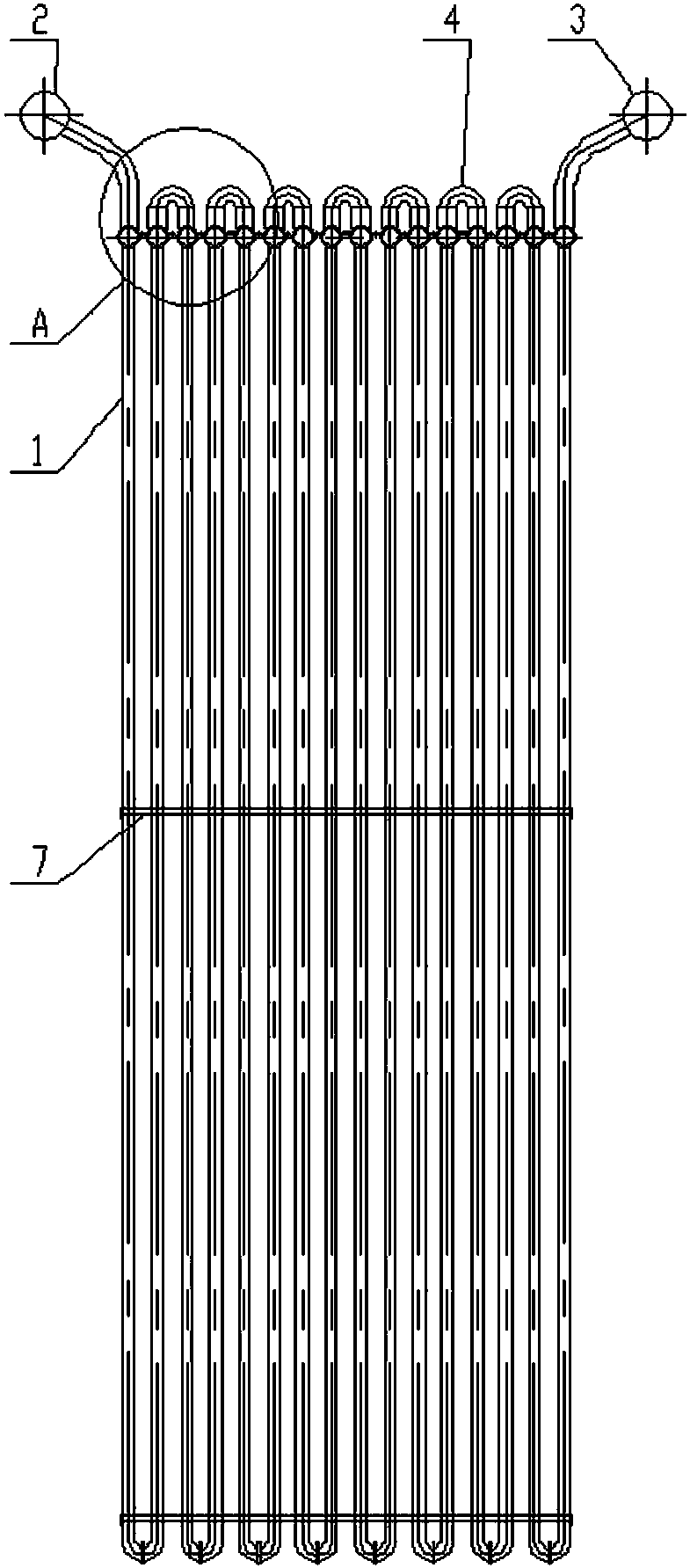
[0036] A U-shaped tube superheater includes a superheater piping system 1 , an inlet header 2 and an outlet header 3 . The inlet header 2 and the outlet header 3 are respectively arranged at both ends of the superheater piping system 1 . The steam enters from the inlet header 2, exchanges heat with the flue gas through the superheater piping system 1, heats the saturated steam into superheated steam, and finally enters the outlet header 3.

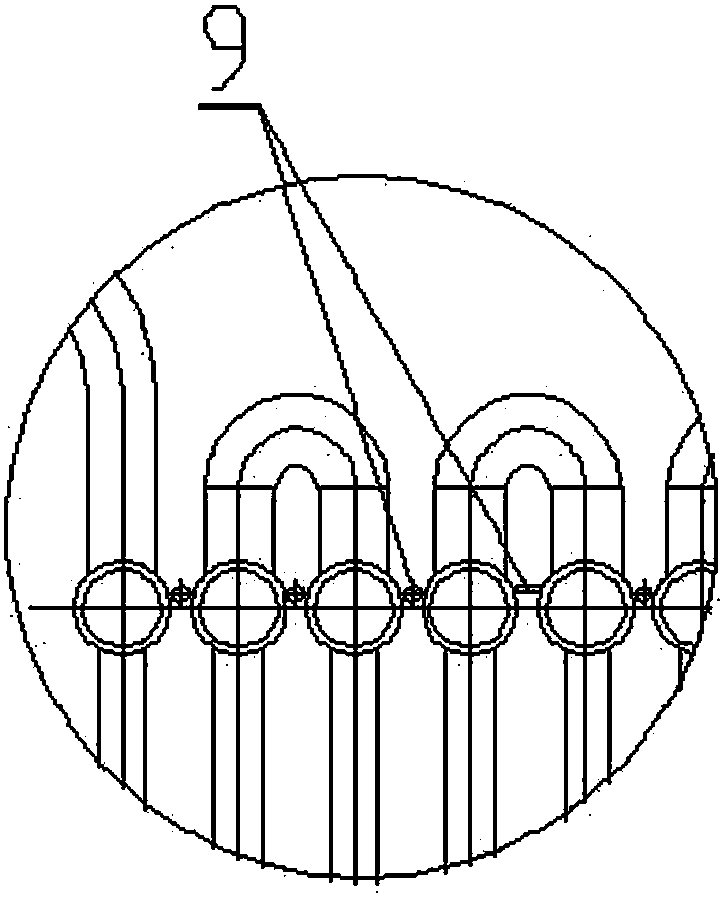
[0037] The superheater piping system 1 includes a U-shaped pipe 5 and a small header 6 .

[0038] The U-shaped pipe 5 is a U-shaped pipe with a single tube circle, which is U-shaped, and is vertically arranged in the horizontal flue. Preferably, the U-shaped tubes 5 are multiple, and the multiple U-shaped tubes 5 are evenly arranged horizontally and vertically, and the U-sha...

Embodiment 2

[0045] A U-shaped tube superheater is arranged in a horizontal flue, and the U-shaped tube superheater of this embodiment adopts a double-pipe coil U-shaped tube type.

[0046] The U-shaped pipe 5 is a U-shaped pipe with double pipe rings, which is U-shaped and includes an inner pipe ring and an outer pipe ring, and both ends of the inner pipe ring and the outer pipe ring are fixedly connected to the small header 6 .

[0047] The rest of the structure of this embodiment is the same as that of Embodiment 1, and will not be repeated here.

[0048] The superheater pipe system of the present application adopts U-shaped pipes, which is beneficial to manufacture, installation and maintenance, and is also beneficial to the sealing of the flue. In order to meet the flue gas velocity in the flue and the steam velocity in the tube within the required range, the U-shaped tube superheater can adopt a single-tube U-shaped tube or a double-tube U-shaped tube according to the specific situat...


PUM


Abstract

The invention discloses a U-shaped pipe superheater and belongs to the technical field of boiler part structure. The U-shaped pipe superheater comprises a superheater pipe system, an inlet header and an outlet header, the inlet header and the outlet header are arranged at two ends of the superheater pipe system respectively, the superheater pipe system comprises small headers and multiple U-shaped pipes, and two ends of each U-shaped pipe are fixed on two adjacent small headers respectively. The U-shaped superheater is simple in structure, convenient to manufacture and maintain, high in safety, small in heat deviation and suitable for arrangement of boilers different in steam flow speed.

Description

technical field [0001] The invention belongs to the technical field of boiler component structures, and in particular relates to a U-shaped tube superheater. Background technique [0002] The horizontal flue of a horizontal waste incineration boiler is usually arranged with a vertical convection superheater, such as Figure 5 with Image 6 As shown, there are two common types of superheaters: serpentine tube superheater and tube row superheater. [0003] Figure 5 Shown is the serpentine tube superheater, when the top of the horizontal flue is equipped with a membrane water cooling wall, the serpentine tube superheater needs to pass through the top water cooling wall. Therefore, the pitch of the serpentine tube is restricted by the pitch of the top water wall, which has a great influence on the heat transfer and dust accumulation of the superheater. If there is no membrane water wall on the top of the horizontal flue, it is necessary to install the top guard plate and pour...

Claims


Application Information

Patent Timeline
Patent Type & Authority Patents(China)
IPC IPC(8): F22G3/00F22G7/12
CPCF22G3/001F22G7/12
Inventor 项光明李荣刘超
Owner 温州伟明环保能源有限公司
Why Eureka
Try Eureka