Piercing tool

a piercing tool and tool body technology, applied in the field of piercing tools, can solve the problems of shortening the depth of the piercing needle in the dermis, unable to reach the dermis, and failing to pierce the piercing needle into the skin,

Inactive Publication Date: 2011-08-02
TERUMO KK
View PDF11 Cites 11 Cited by
  • Summary
  • Abstract
  • Description
  • Claims
  • Application Information

AI Technical Summary

Benefits of technology

[0020]According to the present invention, it is possible to pierce the piercing needle into the skin in a state where the piercing tool is reliably fixed to the body, so that the needlepoint (the medical agent outlet) can reliably reach the predetermined region (e.g., the dermis).

Problems solved by technology

With such a configuration, when attempting to pierce the piercing needle into the skin, there is a possibility that the piercing needle might fail to be pierced into the skin because the whole skin is elastically recessed, or the needlepoint (i.e., the medical agent outlet) of the piercing needle might fail to reach the dermis even if the piercing needle is pierced into the skin.
Further, when the piercing needle is inserted in a direction perpendicular to the dermis, there is a concern that the depth of the piercing needle in the dermis (i.e., insertion depth) may shorten, or the piercing needle may drop out from the dermis during injection of a medical agent when, for example, subjected to some kind of external impact or the like.
Further, when using such devices, since the distance between the insertion opening of the piercing needle formed on the surface of the dermis (i.e., boundary portion of epidermis and dermis) and the medical agent outlet at the tip end of the piercing needle becomes short, there is a concern that the medical agent injected from the medical agent outlet into the dermis may leak from the insertion opening to the outside of the dermis (i.e., to the epidermis).
Further, when deforming the skin to insert the piercing needle into the skin, there is a concern that the piercing needle may not be pierced into the correct region of the skin if the member for deforming the skin is not stably fixed to the skin.

Method used


Image

  • Piercing tool
  • Piercing tool
  • Piercing tool

Examples


first embodiment

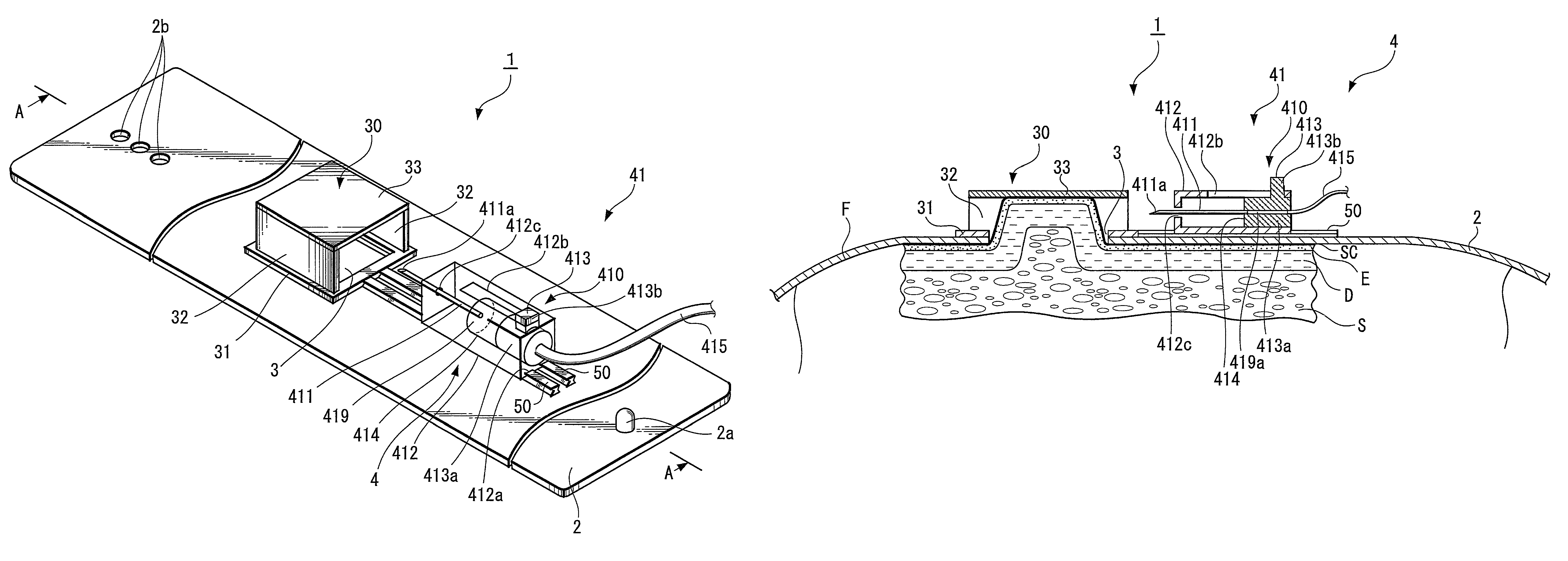
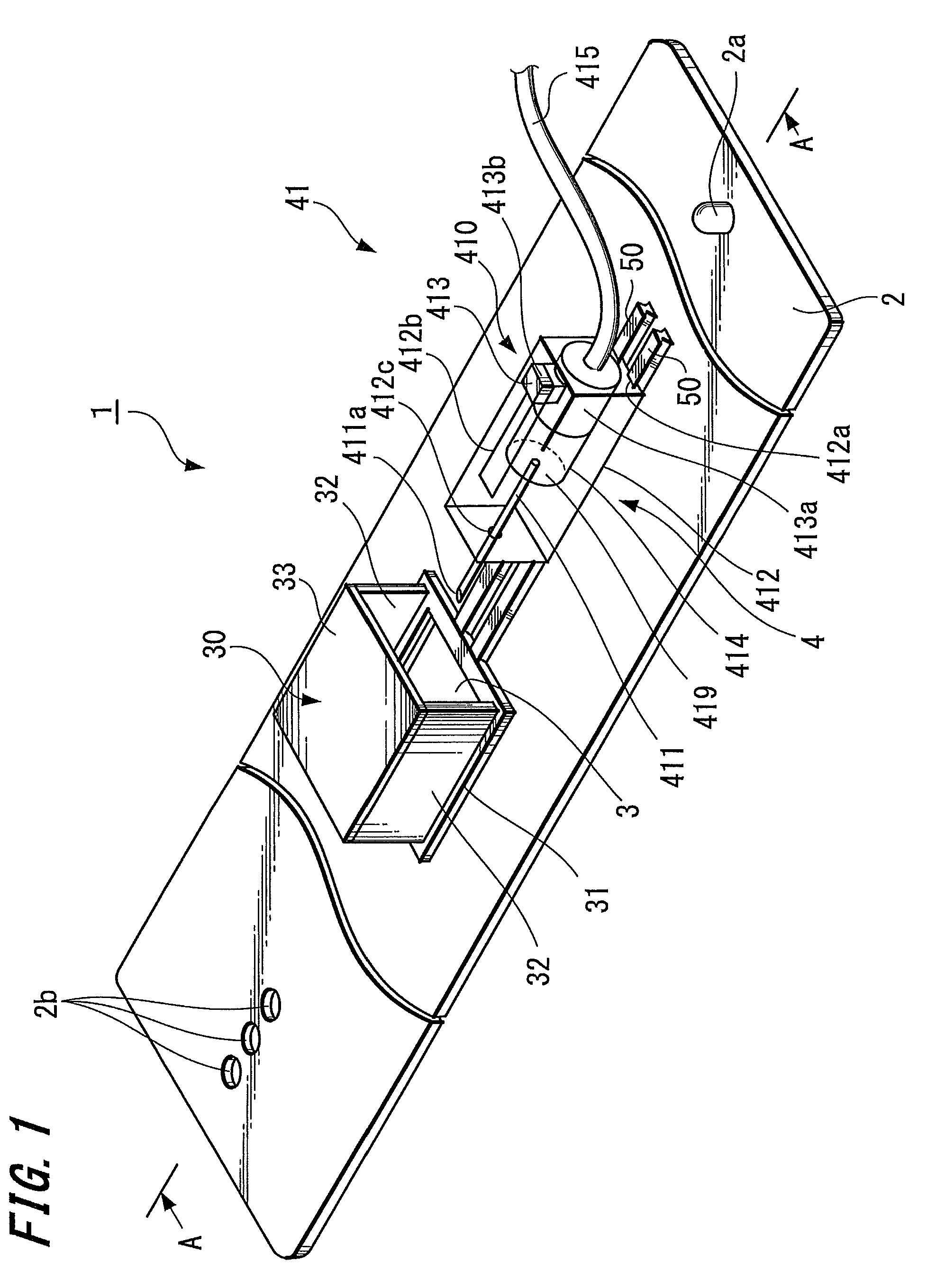
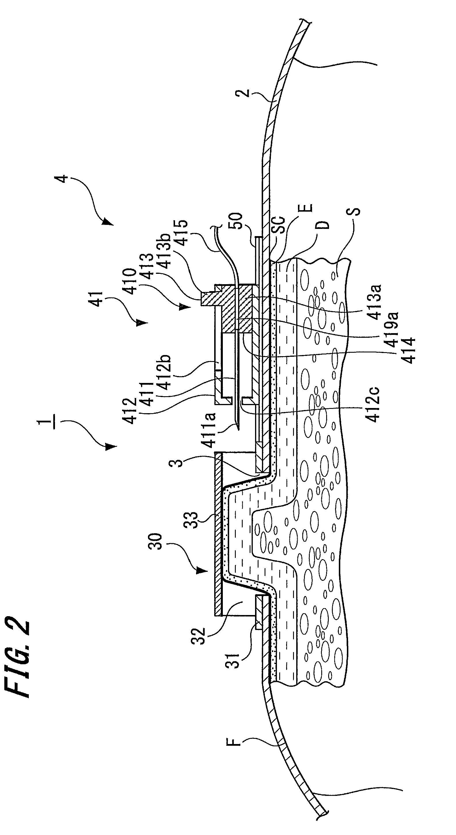
[0032]FIG. 1 is a perspective view showing a piercing tool according to the present invention. FIG. 2 is a cross sectional view taken along line A-A of FIG. 1 when the piercing tool is fixed to the body of a user. FIG. 3 is a cross sectional view for explaining an engaging state between an outer tube and rails of FIG. 1. FIG. 4 illustrates views (cross sectional views) for explaining how to use the piercing tool of FIG. 1.

[0033]Note that, in the following description, the right side of FIGS. 2 and 4 is referred to as “proximal end”, and the left side is referred to as “distal end”.

[0034]As shown in FIGS. 1 and 2, a piercing tool 1, which is a first embodiment of the piercing tool of the present invention, includes a belt-like fixing member 2 for fixing the piercing tool to the body of a user, an opening portion having an opening 3 for upwardly raising skin, a piercing needle moving means 4 for movably holding a piercing needle 411, and the like.

[0035]The belt 2 is a band-like compon...

second embodiment

[0063]FIG. 5 is a perspective view showing a piercing tool according to the present invention. FIG. 6 is a cross sectional view taken along line A-A of FIG. 5 when the piercing tool is fixed to the body. FIG. 7 illustrates views (cross sectional views) for explaining how to use the piercing tool of FIG. 5. Note that, in the following description, the right side of FIGS. 6 and 7 is referred to as “proximal end”, and the left side is referred to as “distal end”.

[0064]As shown in FIGS. 5 and 6, a piercing tool 1, which is a second embodiment of the piercing tool of the present invention, includes a belt-like fixing member 2 for fixing the piercing tool to the body of a user, an opening portion having an opening 3 for upwardly raising skin, a piercing needle moving means 4 for movably holding a piercing needle 411, and the like.

[0065]The belt 2 has the same configuration as that of the piercing tool according to the first embodiment.

[0066]The opening portion for raising skin is formed i...

third embodiment

[0101]FIG. 9 is a perspective view showing a piercing tool according to the present invention.

[0102]As shown in FIG. 9, a piercing tool 1, which is a first embodiment of the piercing tool of the present invention, includes a belt-like fixing member 2 for fixing the piercing tool to the body of a user, an opening portion provided in the central portion of the belt 2 and having an opening 3 for upwardly raising skin, a piercing needle moving means 4 for movably holding a piercing needle 411, and the like. The belt has the same configuration as that of the piercing tool according to the first embodiment.

[0103]The opening portion for raising skin is formed in a central portion of the belt 2. The rectangular shaped opening 3 is formed in the opening portion. The opening 3 is formed so that the longitudinal direction thereof becomes perpendicular to the longitudinal direction of the belt 2. Further, the opening 3 is formed at a position displaced from the central line of the longitudinal ...


PUM


Abstract

A piercing tool (1) can safely and reliably pierce a piercing needle (411) into a skin layer. The piercing tool (1) comprises a belt-like flexible fixing member (2) having an opening (3) formed for raising skin, and a piercing needle moving means (4) mounted on the belt-like fixing member (2) for movably holding the piercing needle (411). By moving the piercing needle moving means (4), the piercing needle (411) is moved so as to be pierced into the skin raised from the opening (3).

Description

TECHNICAL FIELD[0001]The present invention relates to a piercing tool, more particularly to a piercing tool for piercing a skin from the surface of the skin into a predetermined region (e.g., dermis).BACKGROUND ART[0002]It is known that the dermis has high density of capillary blood vessels compared to both the epidermis and the subcutaneous tissue, and has lymph vessel ends. Therefore, directly injected medical agents, in particular, tend to migrate into the blood vessels and / or the lymph vessels, and therefore the absorption speed of the medical agents into the body fluid becomes higher. Particularly, medical agents using macromolecular substance(s) such as hormone, antibody drug, cytokine and the like can be efficiently absorbed into the blood in the dermis. It is also known that the dermis is a place of efficient immunity, which makes it possible to save dose of a vaccine and to strengthen sensitization of a weak vaccine.[0003]Further, it is known that, with respect to a man or ...

Claims


Application Information

Patent Timeline
Patent Type & Authority Patents(United States)
IPC IPC(8): A61M5/42
CPCA61M5/158A61M5/425A61M5/46A61M5/3271A61M5/3287A61M2005/1585
Inventor IMAI, MASAOMI
Owner TERUMO KK
Why Eureka
Try Eureka