
Fast dynamic register

a dynamic register and register technology, applied in logic circuits, pulse clock generators, pulse techniques, etc., can solve the problems of buffers, consuming valuable space and power, and significant disadvantages,

Active Publication Date: 2011-08-02
VIA TECH INC
View PDF62 Cites 11 Cited by
  • Summary
  • Abstract
  • Description
  • Claims
  • Application Information

AI Technical Summary

Benefits of technology

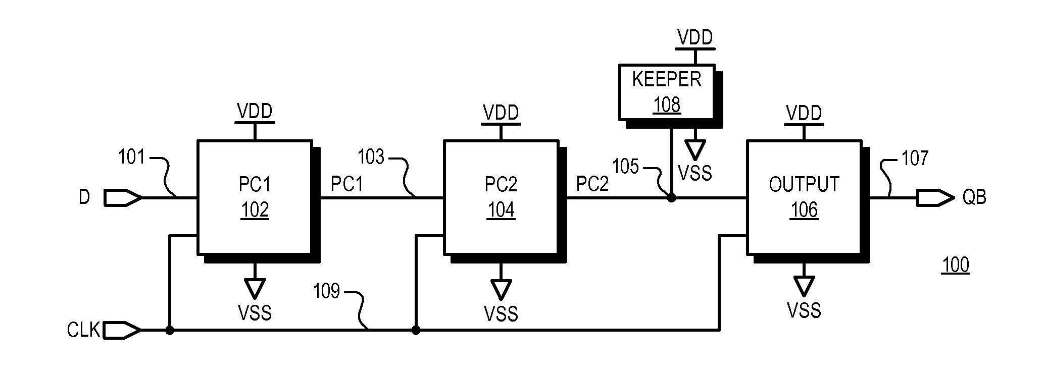
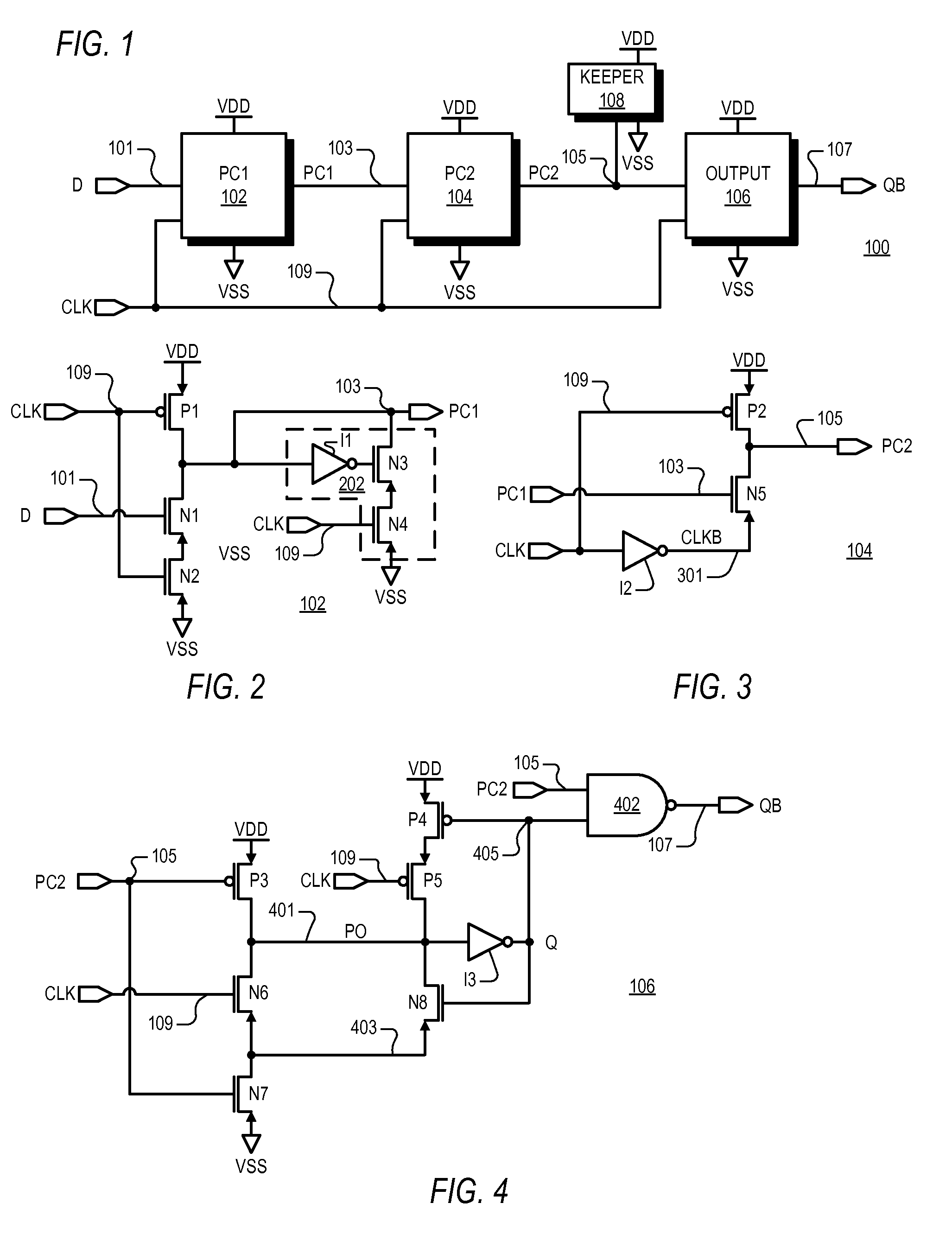
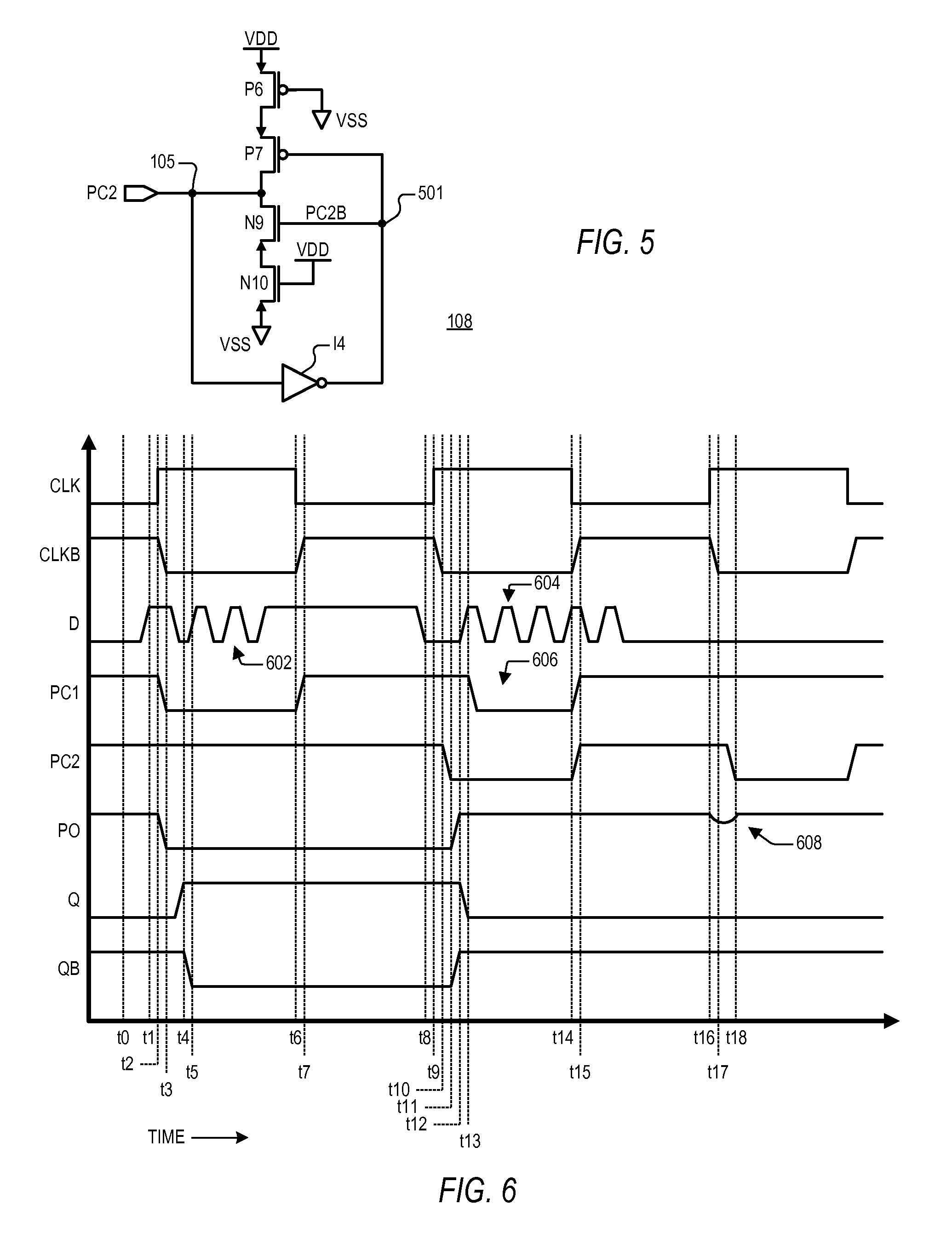
The patent describes a fast dynamic register circuit that can quickly and efficiently register data. The circuit includes multiple precharge circuits, a full keeper circuit, and an output circuit. The precharge circuits precharge a node high while the clock is low, maintain the node high after the clock goes high when a data node is low, discharge the node low if the data node is high, and keep the node discharged if the previous precharge circuit discharged it. The full keeper circuit keeps the state of the previous precharge circuit's output node after it switches state. The output circuit drives the output node to a state based on the precharged node. The circuit can be implemented as a multiple input NOR logic gate or a multiple input NAND logic gate. The technical effect of the circuit is to provide a fast and efficient way to register data.

Problems solved by technology

In many dynamic register circuits, the data had to be held while the clock was at a particular state, which was significantly disadvantageous for certain clock signals at or near 50% duty cycle.
Buffers, however, consume valuable space and power.
A pulse clock generator, however, also consumes valuable space and power.

Method used


Image

  • Fast dynamic register
  • Fast dynamic register
  • Fast dynamic register

Examples


Embodiment Construction

[0026]The following description is presented to enable one of ordinary skill in the art to make and use the present invention as provided within the context of a particular application and its requirements. Various modifications to the preferred embodiment will, however, be apparent to one skilled in the art, and the general principles defined herein may be applied to other embodiments. Therefore, the present invention is not intended to be limited to the particular embodiments shown and described herein, but is to be accorded the widest scope consistent with the principles and novel features herein disclosed.

[0027]The present inventor has observed that dynamic logic circuits often exhibit relatively long setup and / or hold times to ensure proper operation. In many dynamic register circuits, the data had to be held while the clock was at a particular state, which was significantly disadvantageous for certain clock signals at or near 50% duty cycle. In a fast path of a digital circuit...


PUM


Abstract

A fast dynamic register circuit including first and second precharge circuits, a keeper circuit and an output circuit. The first and second precharge circuits each precharge a corresponding one of a pair of precharge nodes and cooperate to minimize setup and hold times. If an input data node is low when the clock goes high, the first precharge node remains high causing the second precharge node to be discharged. Otherwise if the input node is high, the first precharge node is discharged and the second remains charged. Once either precharge node is discharged, the output state of the register remains fixed until the next rising clock edge independent of changes of the input data node. The fast dynamic register may be implemented with multiple inputs to perform common logic operations, such as OR, NOR, AND and NAND logic operations.

Description

BACKGROUND OF THE INVENTION[0001]1. Field of the Invention[0002]The present invention relates to latch and register circuits, and more particularly to a fast dynamic register.[0003]2. Description of the Related Art[0004]Dynamic logic circuits often exhibit relatively long setup and / or hold times to ensure proper operation. In many dynamic register circuits, the data had to be held while the clock was at a particular state, which was significantly disadvantageous for certain clock signals at or near 50% duty cycle. In a fast path of a digital circuit, buffers were often required to hold the data for the requisite amount of time. Buffers, however, consume valuable space and power. One method of reducing the hold time was to provide a pulsed clock generator. A pulse clock generator, however, also consumes valuable space and power.[0005]There is a need for providing a fast dynamic register circuit with minimal setup and hold times without the overhead of buffers and / or pulsed clock circ...

Claims


Application Information

Patent Timeline
Patent Type & Authority Patents(United States)
IPC IPC(8): H03K19/096H03K19/00
CPCH03K19/01728
Inventor LUNDBERG, JAMES R.QURESHI, IMRAN
Owner VIA TECH INC
Learn More