System and method for driving bipolar transistors in switching power conversion

a bipolar junction transistor and switching power conversion technology, applied in the field of integrated circuits, can solve the problems that the system and method of driving a power mosfet cannot be used to drive a power bjt, and the high-voltage power mosfet is often significantly more expensive than the other way around, and achieve the effect of reducing the cost of a switch-mode power converter

Inactive Publication Date: 2011-08-02
ON BRIGHT ELECTRONICS SHANGHAI
View PDF4 Cites 69 Cited by
  • Summary
  • Abstract
  • Description
  • Claims
  • Application Information

AI Technical Summary

Benefits of technology

[0016]Many benefits are achieved by way of the present invention over conventional techniques. For example, some embodiments of the present invention provides a system and method for driving a power bipolar junction transistor in a PWM controlled switch-mode power converter. For example, the switch-mode power converter is an offline fly-back converter or a forward converter. Certain embodiments of the present invention can lower costs for a switch-mode power converter in low power applications.

Problems solved by technology

But the high-voltage power MOSFET is often significantly more expensive than the high-voltage power bipolar NPN transistor.
Therefore, a system and method for driving a power MOSFET often cannot be used for driving a power BJT.

Method used


Image

  • System and method for driving bipolar transistors in switching power conversion
  • System and method for driving bipolar transistors in switching power conversion
  • System and method for driving bipolar transistors in switching power conversion

Examples


Embodiment Construction

[0024]The present invention is directed to integrated circuits. More particularly, the invention provides a system and method for driving bipolar junction transistors. Merely by way of example, the invention has been applied to a power converter. But it would be recognized that the invention has a much broader range of applicability.

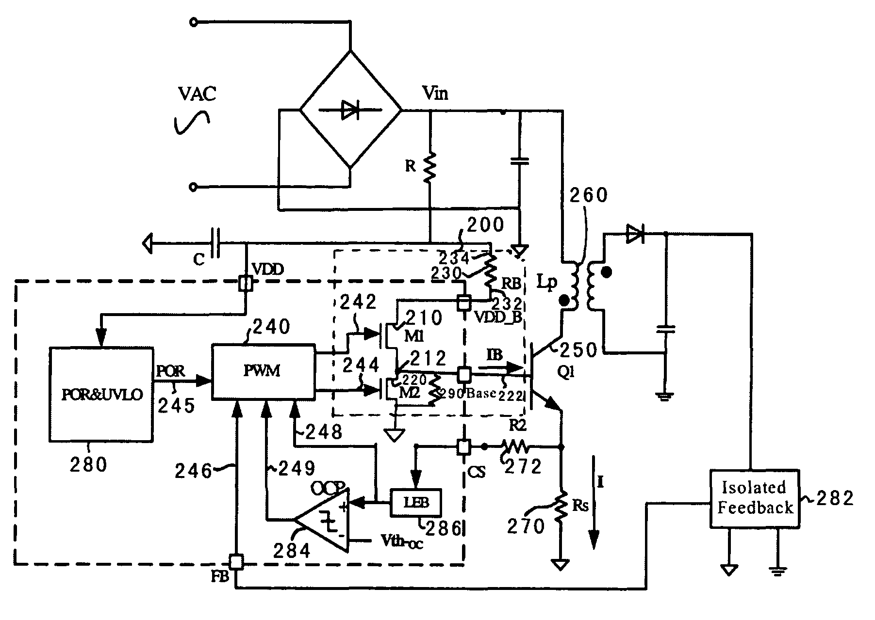
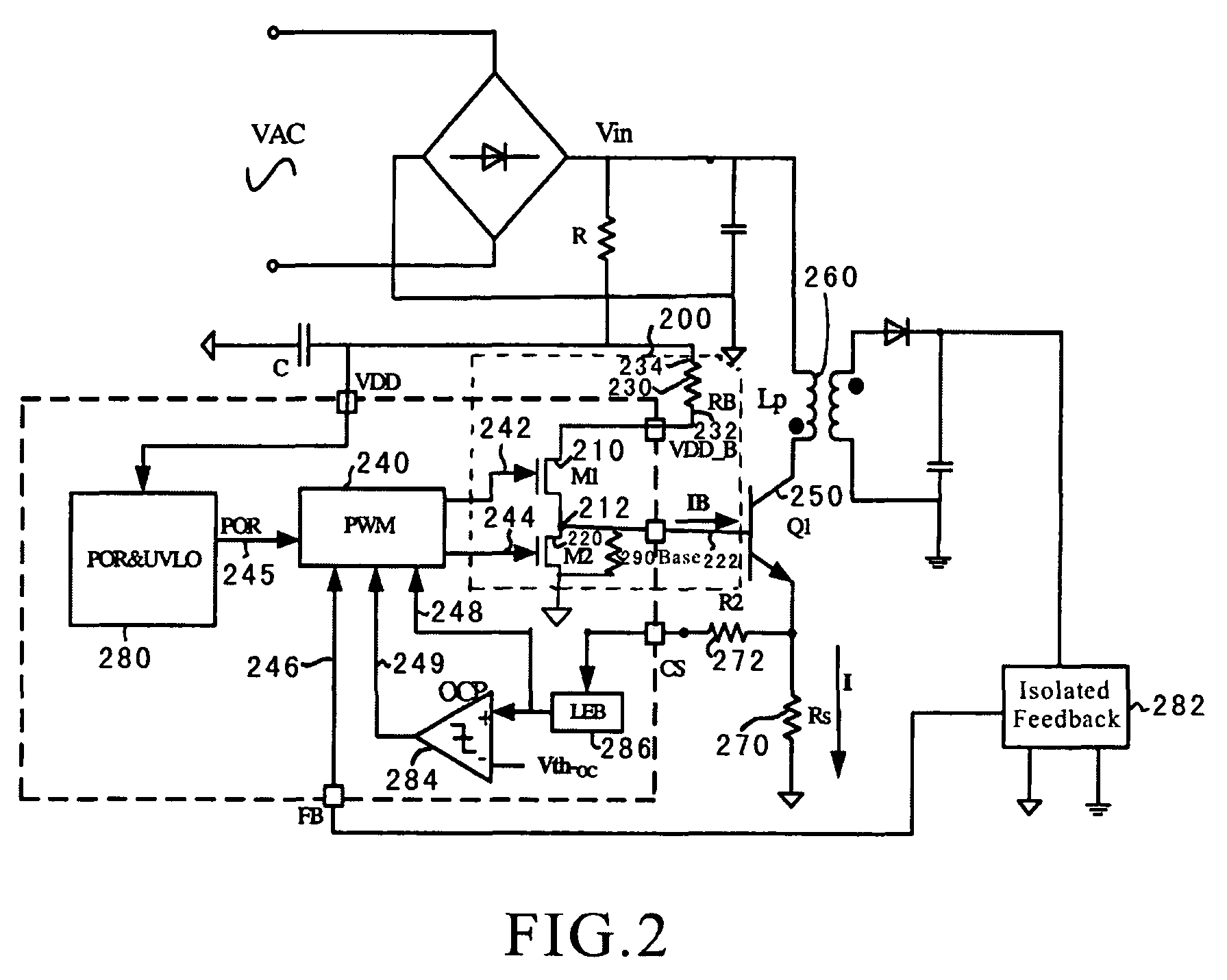
[0025]FIG. 2 is a simplified system for driving bipolar junction transistor according to an embodiment of the present invention. This diagram is merely an example, which should not unduly limit the scope of the claims. One of ordinary skill in the art would recognize many variations, alternatives, and modifications. The system 200 includes transistors 210 and 220, and a resistor 230. Although the above has been shown using a selected group of components for the system 200, there can be many alternatives, modifications, and variations. For example, some of the components may be expanded and / or combined. Other components may be inserted to those noted abov...


PUM


Abstract

A system and method for driving a bipolar junction transistor is provided. The system includes a first transistor including a first gate, a first terminal, and a second terminal. The first gate is configured to receive a first control signal. Additionally, the system includes a second transistor including a second gate, a third terminal, and a fourth terminal. The second gate is configured to receive a second control signal. Moreover, the system includes a first resistor including a fifth terminal and a sixth terminal. The fifth terminal is connected to the first terminal, and the sixth terminal is biased to a first predetermined voltage. The fourth terminal is biased to a second predetermined voltage. The second terminal and the third terminal are connected at a node, and the node is connected to a base for a bipolar junction transistor.

Description

CROSS-REFERENCES TO RELATED APPLICATIONS[0001]This application claims priority to Chinese Patent Application No. 200510111968.2, filed Dec. 21, 2005, entitled “System and Method for Driving Bipolar Transistors in Switching Power Conversion,” by inventors Lieyi Fang, Shifeng Zhao, Zhiliang Chen, and Zhenhua Li, commonly assigned, incorporated by reference herein for all purposes.STATEMENT AS TO RIGHTS TO INVENTIONS MADE UNDER FEDERALLY SPONSORED RESEARCH OR DEVELOPMENT[0002]NOT APPLICABLEREFERENCE TO A “SEQUENCE LISTING,” A TABLE, OR A COMPUTER PROGRAM LISTING APPENDIX SUBMITTED ON A COMPACT DISK[0003]NOT APPLICABLEBACKGROUND OF THE INVENTION[0004]The present invention is directed to integrated circuits. More particularly, the invention provides a system and method for driving bipolar junction transistors. Merely by way of example, the invention has been applied to a power converter. But it would be recognized that the invention has a much broader range of applicability.[0005]Power c...

Claims


Application Information

Patent Timeline
Patent Type & Authority Patents(United States)
IPC IPC(8): H03K17/687
CPCH02M1/08H02M3/33507H03K17/60H03K17/64H03K17/0826H03K17/22H03K17/605
Inventor FANG, LIEYIZHAO, SHIFENGCHEN, ZHILIANGLI, ZHENHUA
Owner ON BRIGHT ELECTRONICS SHANGHAI
Why Eureka
Try Eureka