Anchor/support design for MEMS resonators

a technology of microelectromechanical systems and support structures, applied in the direction of impedence networks, electrical apparatus, etc., can solve the problems of reducing limiting the quality factor (q), and degrading the quality factor (q) of the conventional mems resonator, so as to minimize or substantially reduce the loss of anchors, improve the quality factor (q) of the conventional mems reson

Active Publication Date: 2011-08-02
QORVO US INC
View PDF8 Cites 32 Cited by
  • Summary
  • Abstract
  • Description
  • Claims
  • Application Information

AI Technical Summary

Benefits of technology

[0010]The present invention provides Micro-Electro-Mechanical Systems (MEMS) resonators having support structures that minimize or substantially reduce anchor losses, thereby improving a quality factor (Q) of the MEMS resonators. In general, a MEMS resonator includes a resonator body connected to anchors via support structures. The anchors are connected to or are part of a substrate on which the MEMS resonator is formed. The support structures operate to support the resonator body in free space to enable vibration. The support structures are designed to minimize or substantially reduce energy loss through the anchors into the substrate.
[0011]In one embodiment, the support structures are mechanically symmetric support structures. More specifically, each of the mechanically symmetric support structures includes a mechanically symmetric support component and a coupling beam. The mechanically symmetric support component is coupled to the anchor, and the coupling beam has a first end coupled to the resonator body and a second end coupled to the mechanically symmetric support component. In addition, anchor points for the mechanically symmetric support component may be selected as nodal points on the mechanically symmetric support component at which there is essentially no vibration. As such, the mechanically symmetric support component vibrates as if does not experience any forced boundary condition. As a result, anchor losses are reduced and, therefore, the quality factor of the MEMS resonator is increased.
[0012]In another embodiment, the support structures include coupling beams having first ends connected to the resonator body and second ends connected directly or indirectly to the anchors. Unlike the support beams used in conventional MEMS resonators, a length of each of the coupling beams may be of any desired length and is not limited to being quarter-wavelength (λ / 4). Each of the coupling beams may have a minimum length obtainable with the fabrication process used to fabricate the MEMS resonator. In another embodiment, each of the coupling beams may have a length that is substantially less than quarter-wavelength (λ / 4). The support structures may additionally include mechanically symmetric support components. Each mechanically symmetric support component is coupled to the anchor, and the coupling beam has a first end coupled to the resonator body and a second end coupled to the mechanically symmetric support component. Further, anchor points for the mechanically symmetric support component may be selected as nodal points on the mechanically symmetric support component about which there is symmetric vibration when the MEMS resonator is in vibration mode and at which there is minimal or essentially no vibration when the MEMS resonator is in vibration mode. As a result of the mechanical symmetry of the support structure and the selection of the anchor points as the nodal points having minimal or essentially no vibration, anchor losses are reduced and, therefore, the quality factor of the MEMS resonator is increased.

Problems solved by technology

However, the conventional MEMS resonator 10 having the quarter-wavelength (λ / 4) support beams 18 and 20 has several issues that limit its quality factor (Q) or result in a reduction in its quality factor (Q).
The relatively long support beams 18 and 20 raise fabrication issues and may further result in the resonator body 12 bending and touching the substrate 22, which would of course degrade the quality factor (Q) of the conventional MEMS resonator 10.

Method used


Image

  • Anchor/support design for MEMS resonators
  • Anchor/support design for MEMS resonators
  • Anchor/support design for MEMS resonators

Examples


Embodiment Construction

[0031]The embodiments set forth below represent the necessary information to enable those skilled in the art to practice the invention and illustrate the best mode of practicing the invention. Upon reading the following description in light of the accompanying drawing figures, those skilled in the art will understand the concepts of the invention and will recognize applications of these concepts not particularly addressed herein. It should be understood that these concepts and applications fall within the scope of the disclosure and the accompanying claims.

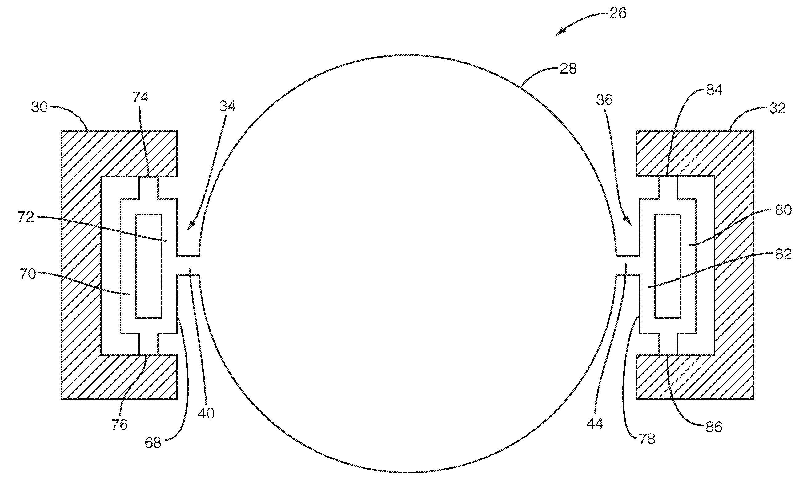
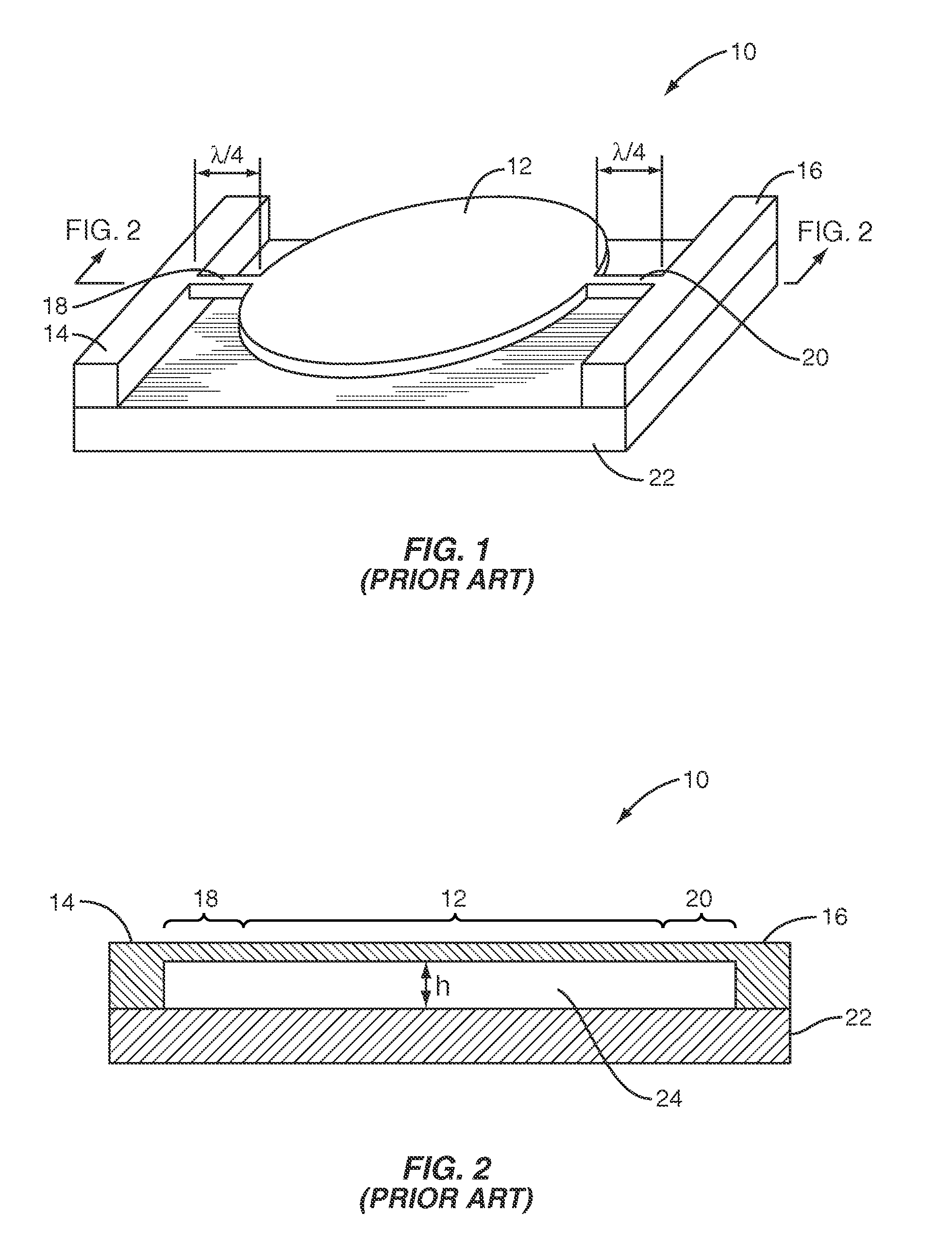
[0032]The present invention provides support, or anchor, structures for MEMS resonators that reduce or eliminate one or more of the anchor losses occurring in the conventional MEMS resonator 10 of FIGS. 1 and 2. Before discussing specific embodiments of the present invention, a mathematical understanding of a MEMS resonator may be beneficial. FIG. 4 is a block diagram of a MEMS resonator 26. The MEMS resonator 26 includes a resona...


PUM


Abstract

Micro-Electro-Mechanical Systems (MEMS) resonator designs having support structures that minimize or substantially reduce anchor losses, thereby improving a quality factor (Q) of the MEMS resonators, are provided. In general, a MEMS resonator includes a resonator body connected to anchors via support structures. The anchors are connected to or are part of a substrate on which the MEMS resonator is formed. The support structures operate to support the resonator body in free space to enable vibration. The support structures are designed to minimize or substantially reduce energy loss through the anchors into the substrate.

Description

RELATED APPLICATIONS[0001]This application claims the benefit of provisional patent application Ser. No. 60 / 942,265, filed Jun. 6, 2007, the disclosure of which is hereby incorporated by reference in its entirety.FIELD OF THE INVENTION[0002]The present invention relates to Micro-Electro-Mechanical Systems (MEMS) resonators and more specifically relates to anchor, or support, structures for MEMS resonators.BACKGROUND OF THE INVENTION[0003]Micro-Electrical-Mechanical Systems (MEMS) resonators have great potential for on-chip selective radio frequency (RF) applications such as oscillators and filters. One of the most important factors in MEMS resonator design is a quality factor (Q) of the MEMS resonator. The quality factor (Q) generally compares a resonant frequency of the MEMS resonator to a rate at which it dissipates energy. The frequency selectivity of the MEMS resonator is dependant on the quality factor (Q). The higher the quality factor (Q), the greater the frequency selectivit...

Claims


Application Information

Patent Timeline
Patent Type & Authority Patents(United States)
IPC IPC(8): H03H9/02H03H9/46
CPCH03H3/0072H03H9/02275H03H9/02338H03H9/2436H03H2009/02496H03H2009/241H03H2009/2442H03H2009/0244
Inventor LEE, SEUNGBAE
Owner QORVO US INC
Why Eureka
Try Eureka