
Radio control transmitter for models

a technology of radio control transmitter and model, which is applied in the direction of electric controller, ignition automatic control, instruments, etc., can solve the problems of limited maximum control range, excessive load on the servo, and still exist the drawbacks described below

Active Publication Date: 2011-08-02
FUTABA CORPORATION
View PDF8 Cites 0 Cited by
  • Summary
  • Abstract
  • Description
  • Claims
  • Application Information

AI Technical Summary

Benefits of technology

[0014]It is an object of the present invention to provide a radio control transmitter for models wherein each of individual control ranges of each of stick levers may be allowed to controlled up to a maximum control range and each of the individual control ranges is limited to maximum control range even when a sum of each of the control ranges exceeds the maximum control range.
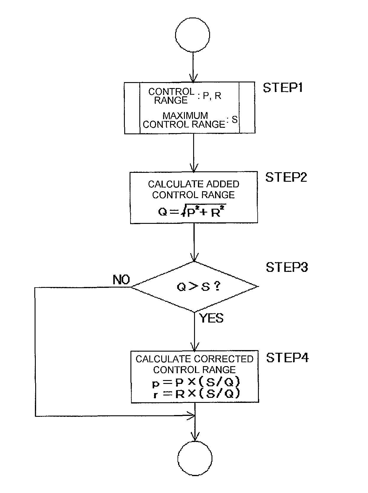
[0015]In order to achieve the above object of the present invention, there is provided a radio control transmitter for a model generating a control signal for controlling a control range of an operating section of an object to be controlled according to a control of a control means, wherein an added control range being a sum of two or more of the control ranges is calculated, whether the added control range exceeds a maximum control range set to correspond to the operating section of the object to be controlled is determined, and the control range is corrected when the added control range exceeds the maximum control range.
[0016]The added control range is a vector sum of the two or more of the control ranges by the control of the control means.
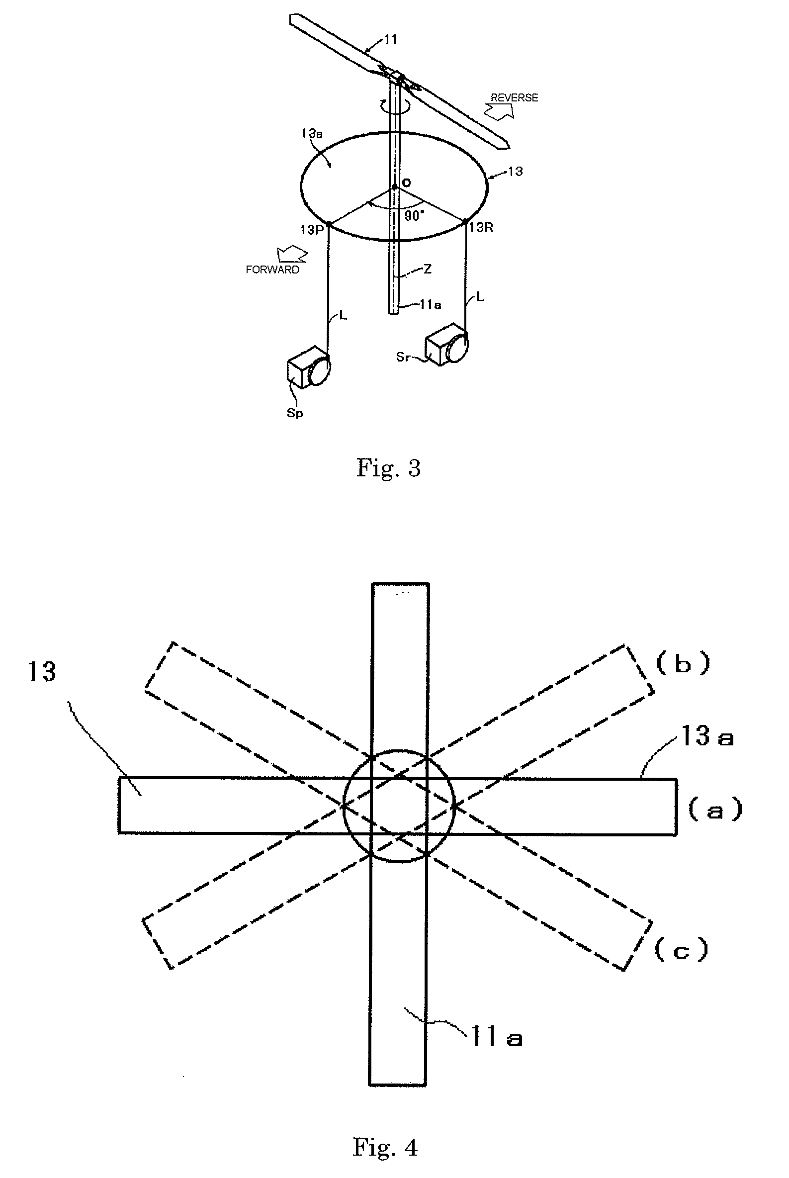
[0017]There is also provided a radio control transmitter for a model generating a control signal for controlling a control range of an operating section of a model helicopter to be controlled according to a control of a control means, wherein an added control range being a sum of the control ranges of a pitch and a roll of a swash plate is calculated, and whether the added control range exceeds a maximum control range set to correspond to the swash plate of the model helicopter to be controlled is determined, and the control range is corrected when the added control range exceeds the maximum control range.
[0018]There is also provided a radio control transmitter for a model generating a control signal for controlling a control range of an operating section of an object to be controlled according to a control of a control means, the transmitter comprising: an added control range calculating means for calculating an added control range being a sum of two or more of the control ranges; a control range determining means for determining whether the added control range exceeds a maximum control range set to correspond to the operating section of the object to be controlled; and a control range correcting means for correcting the control range when the added control range exceeds the maximum control range.

Problems solved by technology

However, the swash plate disposed concentric with the shaft of the main rotor has a limited maximum control range (maximum slant) at which a control range is maximum due to a mechanical limitation.
When the control range of the swash plate is saturated, an excessive load is applied to the servo (the servo for controlling the roll or the pitch) which is an operating source thereof or to a linkage rod connecting the swash plate and the servo.
However, even when the saturation of the swash plate is solved by the stopper which is a mechanical means, a drawback described below still exists.

Method used


Image

  • Radio control transmitter for models
  • Radio control transmitter for models
  • Radio control transmitter for models

Examples


Embodiment Construction

[0026]A preferred embodiment of the present invention will now be described in detail with reference to the accompanied drawings.

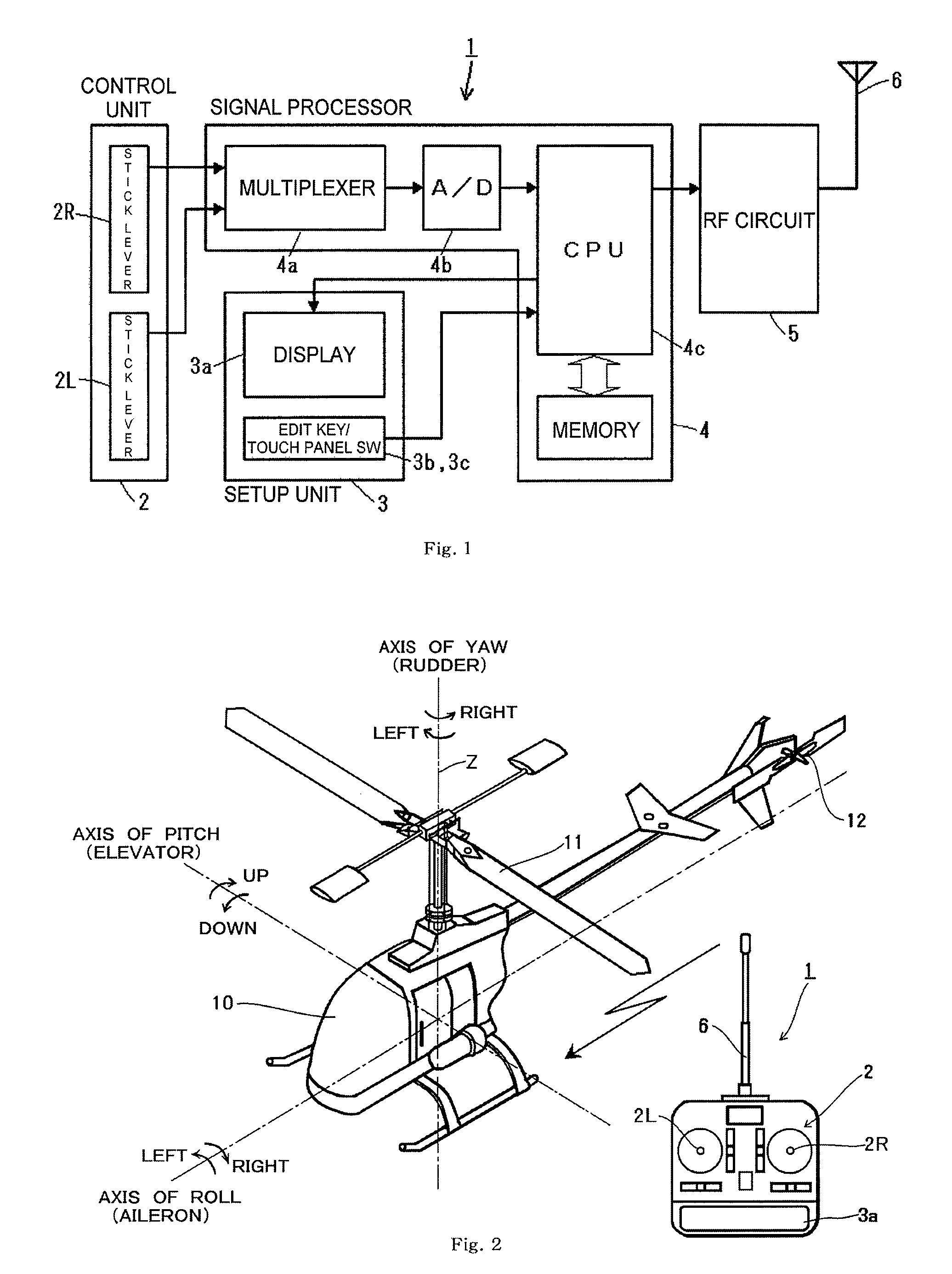
[0027]FIG. 1 is a block diagram schematically illustrating a radio control transmitter for a model in accordance with a preferred embodiment of the present invention.

[0028]As shown in FIG. 1, a transmitter 1 comprises a control unit 2, a setup unit 3, a signal processor 4, a high frequency circuit 5 and an antenna 6.

[0029]The control unit 2 comprises a stick lever 2R and a stick lever 2L. The stick lever 2R and the stick lever 2L outputs an analog signal as a control signal according to a control by shifting in up, down, left and right directions to vary a resistance value of a variable resistor.

[0030]The setup unit 3 for setting up or changing a configuration comprises a display 3a such as a liquid crystal display and a plurality of edit keys 3b disposed in main body of the transmitter 1 or a touch panel switch 3c disposed on a display screen of the displ...


PUM


Abstract

A radio control transmitter for a model is disclosed wherein a control range is limited to not to exceed a maximum control range without using a mechanical means. In accordance with the transmitter, an added control range being a sum of two or more of the control ranges is calculated, whether the added control range exceeds a maximum control range set to correspond to the operating section of the object to be controlled is determined, and the control range is corrected when the added control range exceeds the maximum control range.

Description

CROSS REFERENCE TO RELATED APPLICATIONS[0001]This application claims priority under 35 U.S.C. §119 to Application No. JP2006-248803 filed on Sep. 14, 2006, entitled “Radio Control Transmitter for Models,” the entire contents of which are hereby incorporated by reference.FIELD OF THE INVENTION[0002]The present invention relates to a radio control transmitter for remotely controlling an object to be controlled by controlling a control signal transmitted to the object to be controlled through a radio frequency wave, and in particular to a radio control transmitter suitable for remotely controlling an object to be controlled such as a model plane, a model helicopter, a model car or a model boat.BACKGROUND[0003]A radio control transmitter for a model controlling an object to be controlled such as a model plane, a model helicopter, a model car or a model boat comprises a stick lever operating a main controller and various levers and switches operating as an auxiliary controller. Each of t...

Claims


Application Information

Patent Timeline
Patent Type & Authority Patents(United States)
IPC IPC(8): H04L17/02
CPCA63H30/04
Inventor YAMAMOTO, MICHIOTOYOTOMI, KOTA
Owner FUTABA CORPORATION
Learn More