Aiming telescope having a range finder

a telescope and range finder technology, applied in the field of aiming telescopes, can solve the problems of loss of range, reflection of the emitted laser beam at the objective lens, and loss of parallel or the coinciding line of sight and of the laser beam, and achieve the effects of compact design, low weight and high precision

Inactive Publication Date: 2011-08-02
CARL ZEISS SPORTS OPTICS
View PDF16 Cites 61 Cited by
  • Summary
  • Abstract
  • Description
  • Claims
  • Application Information

AI Technical Summary

Benefits of technology

[0022]It is an object underlying the invention to improve an aiming telescope of the type specified at the outset, such that the afore-mentioned disadvantages are avoided. In particular, an aiming telescope shall be provided having a compact design, a low weight, and, nevertheless, a high precision for what concerns the range measurement even at large distances.

Problems solved by technology

Now, when the line of sight of the aiming telescope is adjusted by adjusting the aiming mark through actuation of the turrets, the parallelism or the coinciding of the line of sight and of the laser beam gets lost.
In any event, this results in a loss of range.
This results in reflections of the emitted laser beam at the objective lens and to errors within the received signal (so-called auto-errors).
On the one hand, the direct rigid coupling between the reticle and the biconcave lens only allows a very coarse readjustment of the emitted measuring laser beam of the laser emitter relative to the line of sight.
On the other hand, the emitted measuring laser beam wanders out of the optical center of the biconcave lens when only the lens is transversely shifted whereas the laser emitter as well as the further lenses of the Galilei-system are held stationary with the housing, which results in an optical distortion of the emitted measuring beam.
Further, the mechanical construction is difficult to make when the reticle is arranged in the vicinity of the eyepiece, whereas the laser emitter shall be located as close as possible to the objective lens.
Finally, the utilization of a laser emitter with a downstream optical system is disadvantageous also in view of the corresponding weight, and the optical system causes a considerable distance between the optical axes of the laser emitter and of the aiming telescope which, in turn, results in considerable parallax errors.
This device, therefore, has the same disadvantage as already discussed above, namely that the emitted measuring beam is optically distorted during pivoting.

Method used


Image

  • Aiming telescope having a range finder
  • Aiming telescope having a range finder
  • Aiming telescope having a range finder

Examples


Embodiment Construction

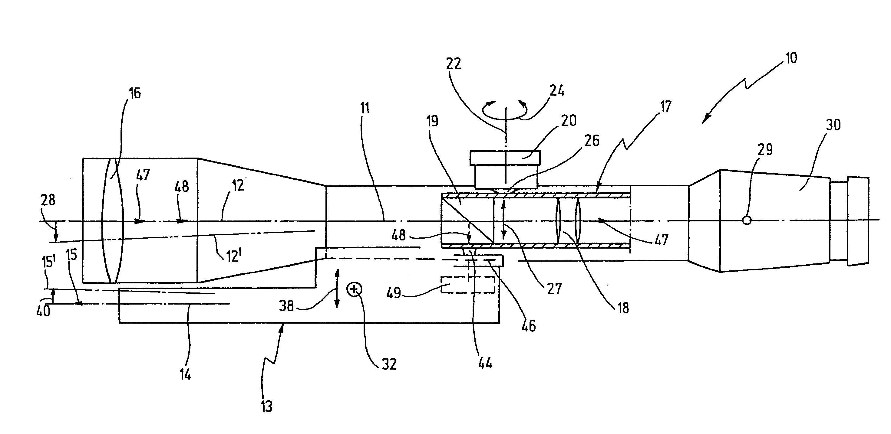
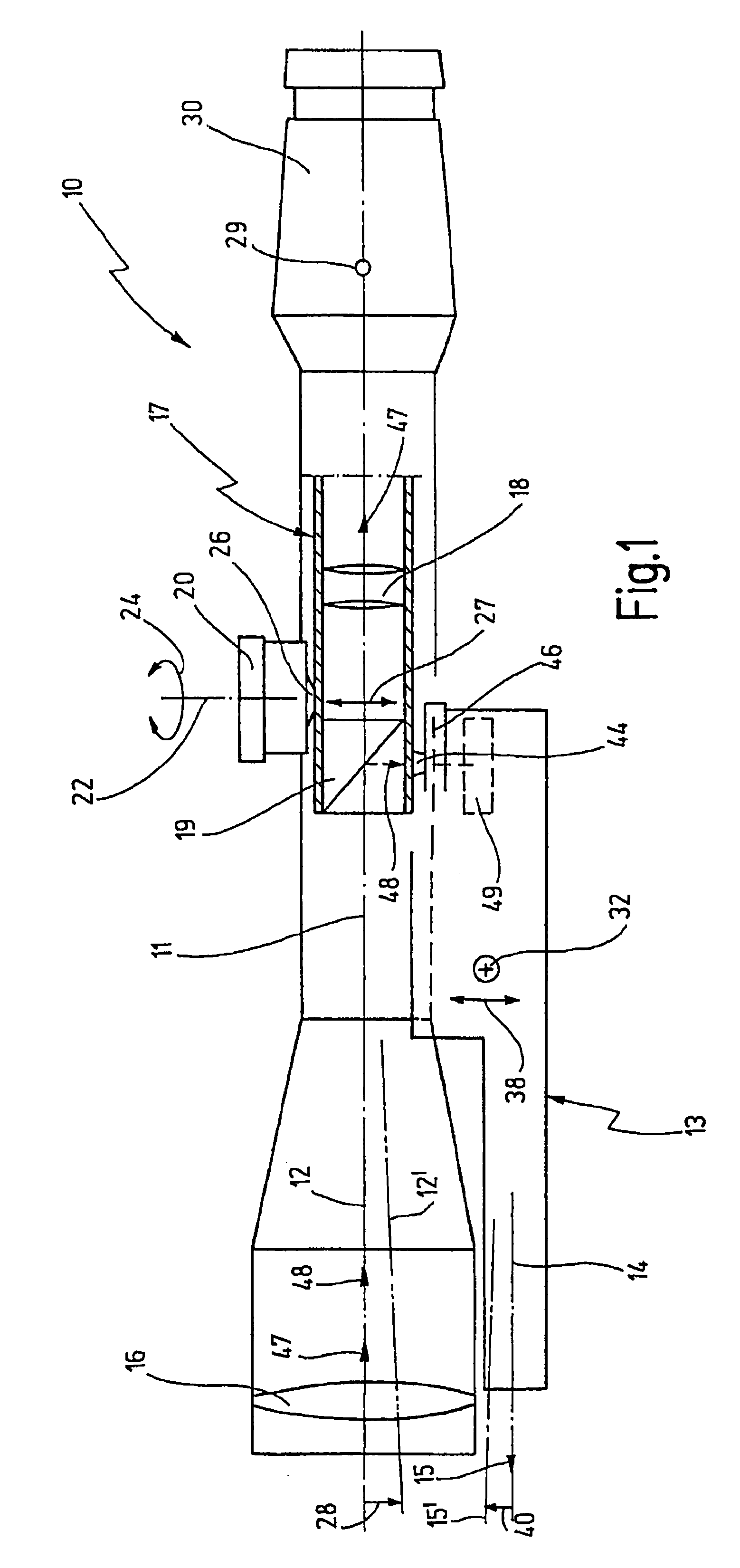
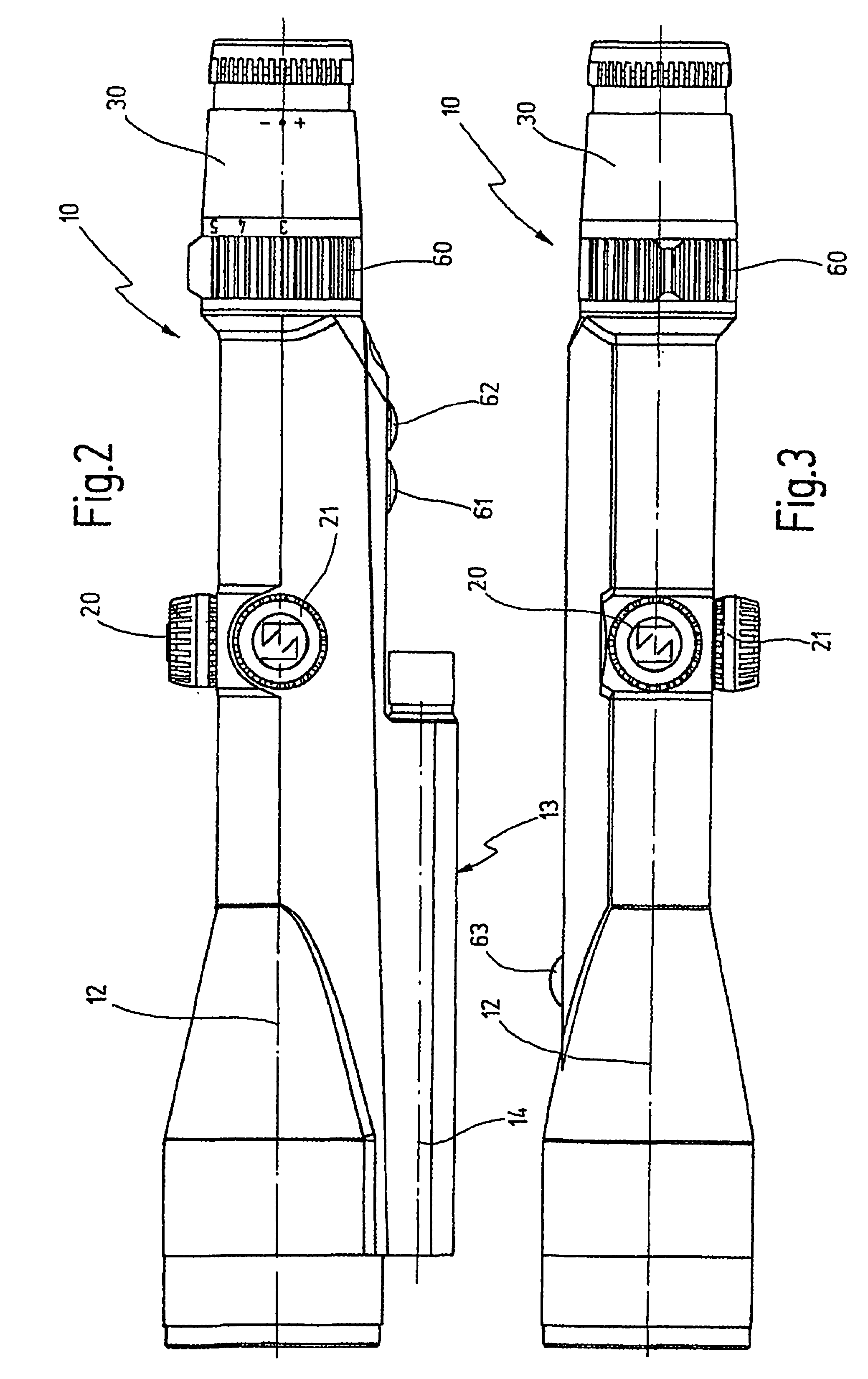
[0119]In FIG. 1 reference numeral 10 as a whole designates an aiming telescope. The aiming telescope 10 has an optical axis 11. A line of sight 12 of the aiming telescope 10 coincides with the optical axis 11 in the basic operational position of the aiming telescope 10.

[0120]A range finder 13, in particular a laser range finder, is mounted to the aiming telescope 10. The range finder 13 has a longitudinal axis 14 and is mounted to the aiming telescope 10 such that an emitted measuring beam 15 emanating from the range finder 13 along the longitudinal axis 14 is normally parallel to the optical axis 11 and, hence, also parallel to the line of sight 12. Thereby the emitted measuring beam 15 impinges on the target exactly at the point lying on the line of sight 12.

[0121]An inner tube 17 being adapted to be pivoted relative to the optical axis 11 is arranged within the aiming telescope 10 on the side opposite to an objective lens 16. The inner tube 17 is adapted to be pivoted with its ob...


PUM


Abstract

An aiming telescope has an optical axis and a line of sight. Turrets are provided for adjusting the direction of the line of sight. A range finder is structurally connected with the aiming telescope. The range finder has a light source for emitting an emitted measuring beam. The emitted measuring beam runs outside the aiming telescope. It has a direction coinciding essentially with the direction of the line of sight. A transmission is provided for automatically adjusting the direction of the emitted measuring beam when the direction of the line of sight is adjusted. The light source is pivotably mounted on the aiming telescope. The transmission acts between the aiming telescope and the light source.

Description

CROSS REFERENCE TO OTHER APPLICATIONS[0001]The present application is a continuation of pending International patent application PCT / EP2006 / 0001142, filed Feb. 9, 2006 which designates the United States and was published in German, and which claims priority of German patent application 10 2005 007 916.4, filed Feb. 10, 2005. The disclosure of the above application is incorporated herein by reference.FIELD OF THE INVENTION[0002]The invention is related to the field of aiming telescopes.[0003]More specifically, the invention is related to aiming telescopes having an optical axis and a line of sight, first means for adjusting the direction of the line of sight, a range finder being structurally connected with the aiming telescope, the range finder having a light source for emitting an emitted measuring beam, the emitted measuring beam running outside the aiming telescope and having a direction coinciding essentially with the direction of the line of sight, and second means for automati...

Claims


Application Information

Patent Timeline
Patent Type & Authority Patents(United States)
IPC IPC(8): G01C3/08
CPCF41G3/065F41G3/326G01S7/4812G01S7/497G01S17/023G01S17/86
Inventor SCHLIERBACH, ARMINPOLZER, GERDHELLER, MATTHIAS
Owner CARL ZEISS SPORTS OPTICS
Why Eureka
Try Eureka