
Meniscus prosthetic device selection and implantation methods

a prosthetic device and meniscus technology, applied in the field of medical prosthetic can solve the problems of not being satisfactory in all respects, devices, systems and methods, pain and arthritis, etc., and achieve the effects of increasing thickness, increasing thickness, and increasing melting poin

Active Publication Date: 2011-08-02
ACTIVE IMPLANTS LLC
View PDF114 Cites 10 Cited by
  • Summary
  • Abstract
  • Description
  • Claims
  • Application Information

AI Technical Summary

Benefits of technology

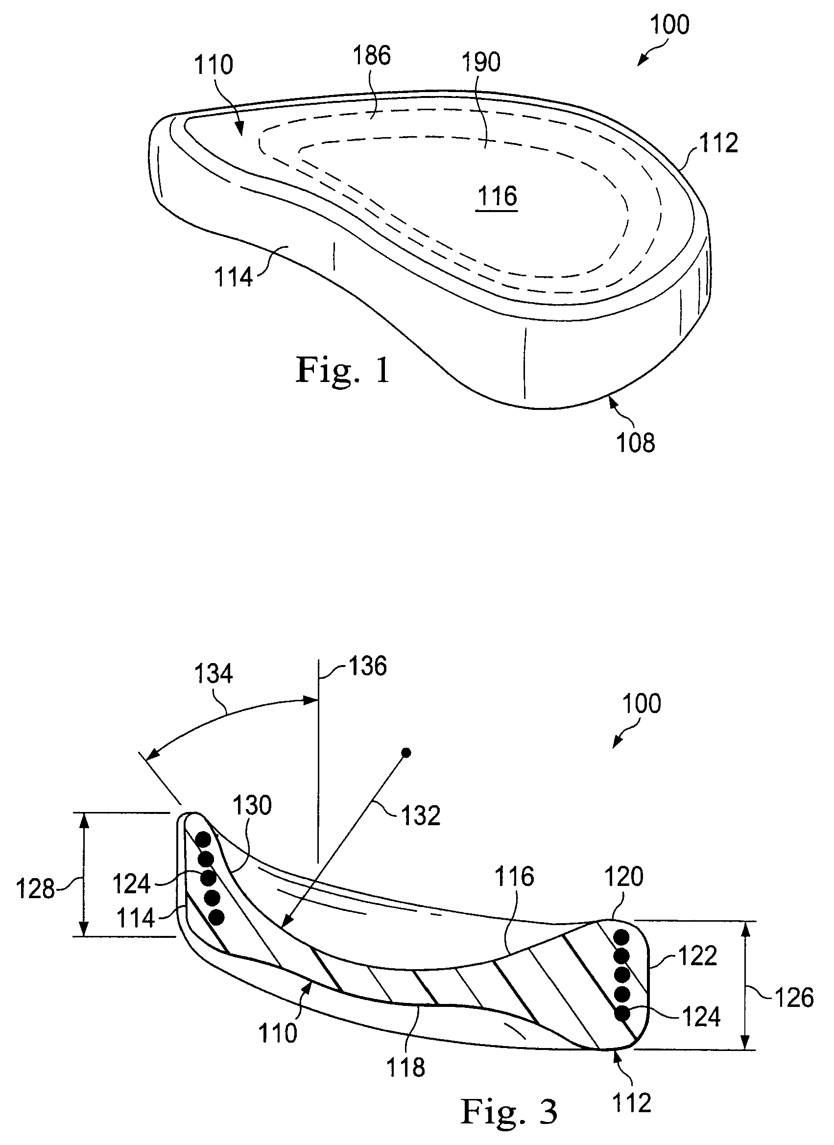
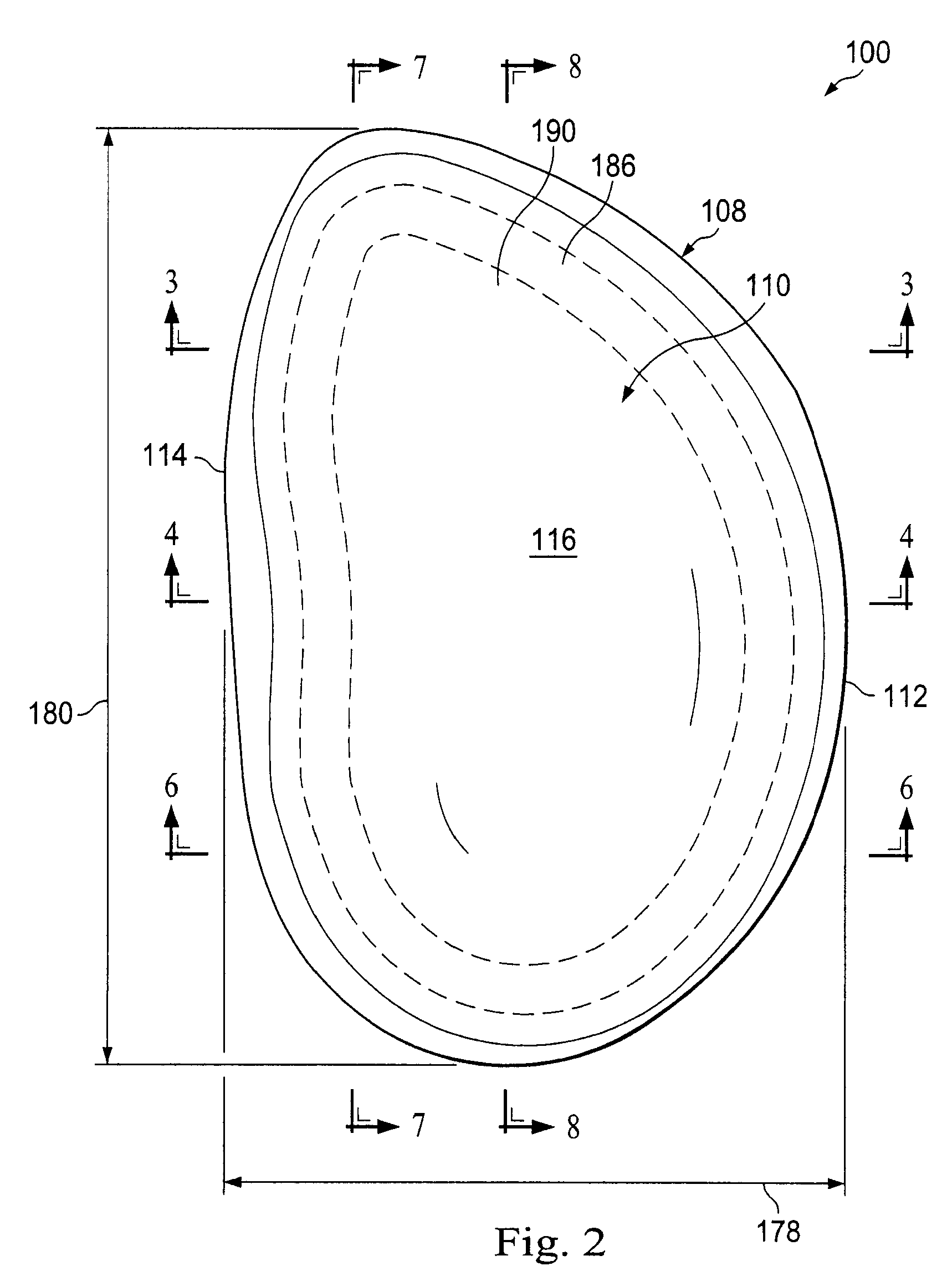
In another embodiment, a meniscus prosthetic device is disclosed. The meniscus prosthetic devices comprises a central portion having an upper surface for engagement with a portion of a femur and an opposing lower surface for engagement with a portion of a tibia. An outer portion surrounds the central portion and has an increased thickness relative to the central portion. The outer portion comprises a first section having a generally semi-ellipsoidal profile similar to that of a natural meniscus and a second section extending between first and second ends of the first section. The second section is sized and shaped to engage a femur notch to secure the meniscus prosthetic device within a knee joint without penetrating bone. The second section has an upper-inner surface tapering into the upper surface of the central portion. The upper-inner surface is defined by a varying radius of curvature along a length of the second section.
In another embodiment, a meniscus implant for secured positioning within a knee joint without requiring the penetration of bone is disclosed. The meniscus implant comprises a central portion having an upper surface for engagement with a portion of a femur and an opposing lower surface for engagement with a portion of a tibia. An outer portion surrounds the central portion and has an increased thickness relative to the central portion. The outer portion comprises a first section having a generally semi-ellipsoidal profile similar to that of a natural meniscus and a second section extending between first and second ends of the first section. The second section has a first region adjacent the first end of the first section, a second region adjacent the second end of the first section, and third region between the first and second regions. The first region of the second section has a height between about 4 mm and about 15 mm, a first radius of curvature along the length of the second section between about 5 mm and about 70 mm, and a second radius of curvature perpendicular to the length of the second section between about 10 mm and about 100 mm. The second region of the second section has a height between about 4 mm and about 15 mm, a third radius of curvature along the length of the second section between about 5 mm and about 50 mm, and a fourth radius of curvature perpendicular to the length of the second section between about 5 mm and about 70 mm. The third region of the second section has a height between about 4 mm and about 15 mm and a first radius of curvature along the length of the second section between about 10 mm and about 30 mm.
In another embodiment, a method of manufacturing a meniscus prosthetic device is disclosed. The method comprises injection molding a core having an upper surface, a lower surface opposite the upper surface, and an outer surface disposed between the upper and lower surfaces. The outer surface defines a plurality of recesses. The method also includes winding reinforcing fiber into at least one of the plurality of recesses of the outer surface and injection molding an outer portion around the outer surface and the reinforcing fibers to secure the reinforcing fibers therein. In one aspect, the material of the core has a higher melting point than the reinforcing fibers.
In another embodiment, a method of manufacturing a prosthetic device is disclosed. The method comprises injecting a polycar

Problems solved by technology

Damage to the meniscus can cause pain and arthritis.
While existing devices, systems, and methods have attempted to address these issues, they have not been satisfactory in all respects.

Method used


Image

  • Meniscus prosthetic device selection and implantation methods
  • Meniscus prosthetic device selection and implantation methods
  • Meniscus prosthetic device selection and implantation methods

Examples


Embodiment Construction

For the purposes of promoting an understanding of the principles of the present disclosure, reference will now be made to the embodiments illustrated in the drawings, and specific language will be used to describe the illustrated embodiments. It is nevertheless understood that no limitation of the scope of the disclosure is intended. Any and all alterations or modifications to the described devices, instruments, and / or methods, as well as any further application of the principles of the present disclosure that would be apparent to one skilled in the art are encompassed by the present disclosure even if not explicitly discussed herein. Further, it is fully contemplated that the features, components, and / or steps described with respect to one embodiment may be combined with the features, components, and / or steps described with respect to other embodiments of the present disclosure.

Prosthetic Devices

Referring now to FIGS. 1, 2, 3, 4, 5, 6, 7, 8, 9, and 10 shown therein is a prosthetic ...


PUM


Abstract

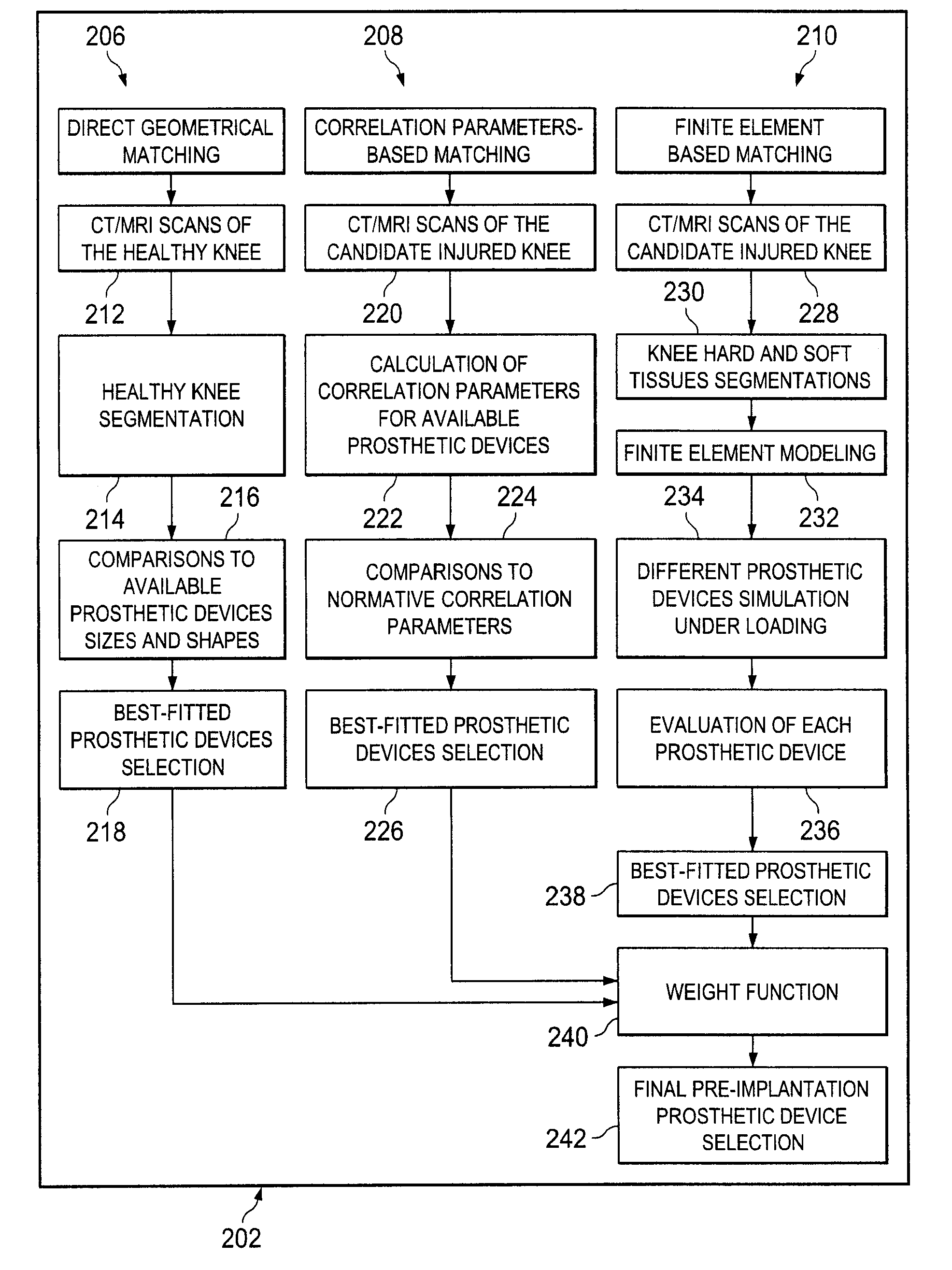
Methods of selecting and implanting prosthetic devices for use as a replacement meniscus are disclosed. The selection methods include a pre-implantation selection method and a during-implantation selection method. The pre-implantation selection method includes a direct geometrical matching process, a correlation parameters-based matching process, and a finite element-based matching process. The implant identified by the pre-implantation selection method is then confirmed to be a suitable implant in the during-implantation selection method. Methods of implanting meniscus prosthetic devices are also disclosed.

Description

BACKGROUNDThe present disclosure generally relates to medical prosthetic devices, systems, and methods. More specifically, in some instances the present disclosure relates to prosthetic devices that replace at least part of the functionality of the natural meniscus. Each knee has two menisci, a lateral meniscus and a medial meniscus. Each meniscus is a crescent-shaped fibrocartilaginous tissue attached to the tibia at an anterior and a posterior horn. Damage to the meniscus can cause pain and arthritis. Accordingly, in some instances it is desirable to replace the damaged natural meniscus with a prosthetic device. In some instances the prosthetic devices of the present disclosure are configured to be surgically implanted into a knee joint to replace or augment the natural meniscus. It is important that the prosthetic device be of the appropriate size and functionality for the intended patient. In some instances the methods of the present disclosure identify suitable prosthetic devic...

Claims


Application Information

Patent Timeline
IPC IPC(8): G06F9/455
CPCA61F2/3872A61F2/4684A61B19/50A61B2019/508A61F2/30965A61F2002/30014A61F2002/30064A61F2002/30065A61F2002/30069A61F2002/30329A61F2002/30563A61F2002/30565A61F2002/30616A61F2002/30673A61F2002/30841A61F2002/30884A61F2002/30906A61F2002/3093A61F2002/30945A61F2002/30948A61F2002/30955A61F2002/30957A61F2002/30983A61F2002/3895A61F2210/0071A61F2220/0025A61F2250/0018A61B34/10A61B2034/108B33Y50/00B33Y80/00A61F2220/0008A61F2240/008A61F2250/0064A61F2/3094A61F2002/30943A61F2/461
Inventor LINDER-GANZ, ERANSHTERLING, AVRAHAMWEISSBERG, NOAM
Owner ACTIVE IMPLANTS LLC
Learn More