Rotary thermal recycling system

a technology of thermal recycling and rotary shaft, which is applied in the direction of furnaces, charging, and ways, can solve the problems of aggravating wear on the surface of augers, affecting the efficiency of thermal processing, and affecting the efficiency of thermal processing, and achieves the effect of slow gradual elevation of product temperatur

Inactive Publication Date: 2011-08-09
COLLETTE JERRY R +1
View PDF17 Cites 33 Cited by
  • Summary
  • Abstract
  • Description
  • Claims
  • Application Information

AI Technical Summary

Benefits of technology

[0002]Current technologies, machinery and systems have been invented, and patents applied for that exist for the purpose of heating materials via conduction while controlling the atmosphere within the heating vessel, especially oxygen (O2) content. Heat transfer fluids such as chemicals, thermal oils, and salts, as well as heated exhaust gasses and hot air are heated via a fired heat exchanger, gasification process or oil heater and are then pumped through hollow cavities in screw augers, hollow troughs, jackets, pipes, coils and other heat exchange devices to allow a slow gradual elevation of product temperature and moisture removal.

Problems solved by technology

The primary RAP Saver Systems patent applications limit the conductive heating surfaces temperatures and limit the potential for over heating the material being heated (i.e. used asphalt paving, RAP) to approximately 400° F. to 550° F. since heat transfer fluid is inherently limited to a 600° F. continuous operating temperature.
In the early stages of empirical testing and daily operations with newly designed prototype test units, aggressive wear was noted on the auger flighting and inner trough surfaces.
This may result in considerable surface wear.
After extensive testing with a variety of different materials, it became apparent that there were many higher temperature applications where various types of process materials would have to be heated (via conduction) to temperatures in the 500° F. to 1,100° F. range, thereby greatly exacerbating wear issues and requiring even more exotic metallurgy and abrasion resistant metallurgy.

Method used


Image

  • Rotary thermal recycling system
  • Rotary thermal recycling system
  • Rotary thermal recycling system

Examples


Embodiment Construction

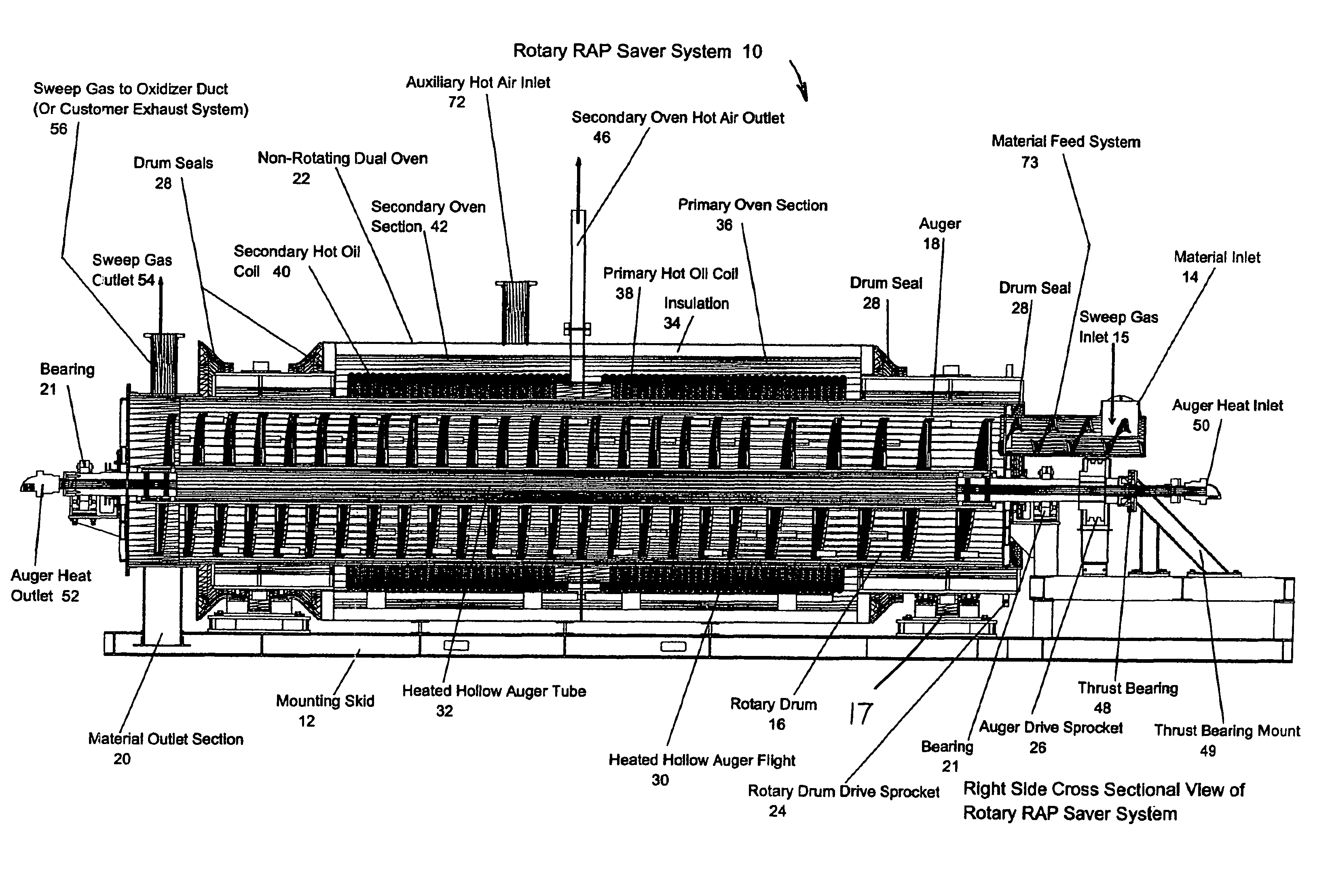
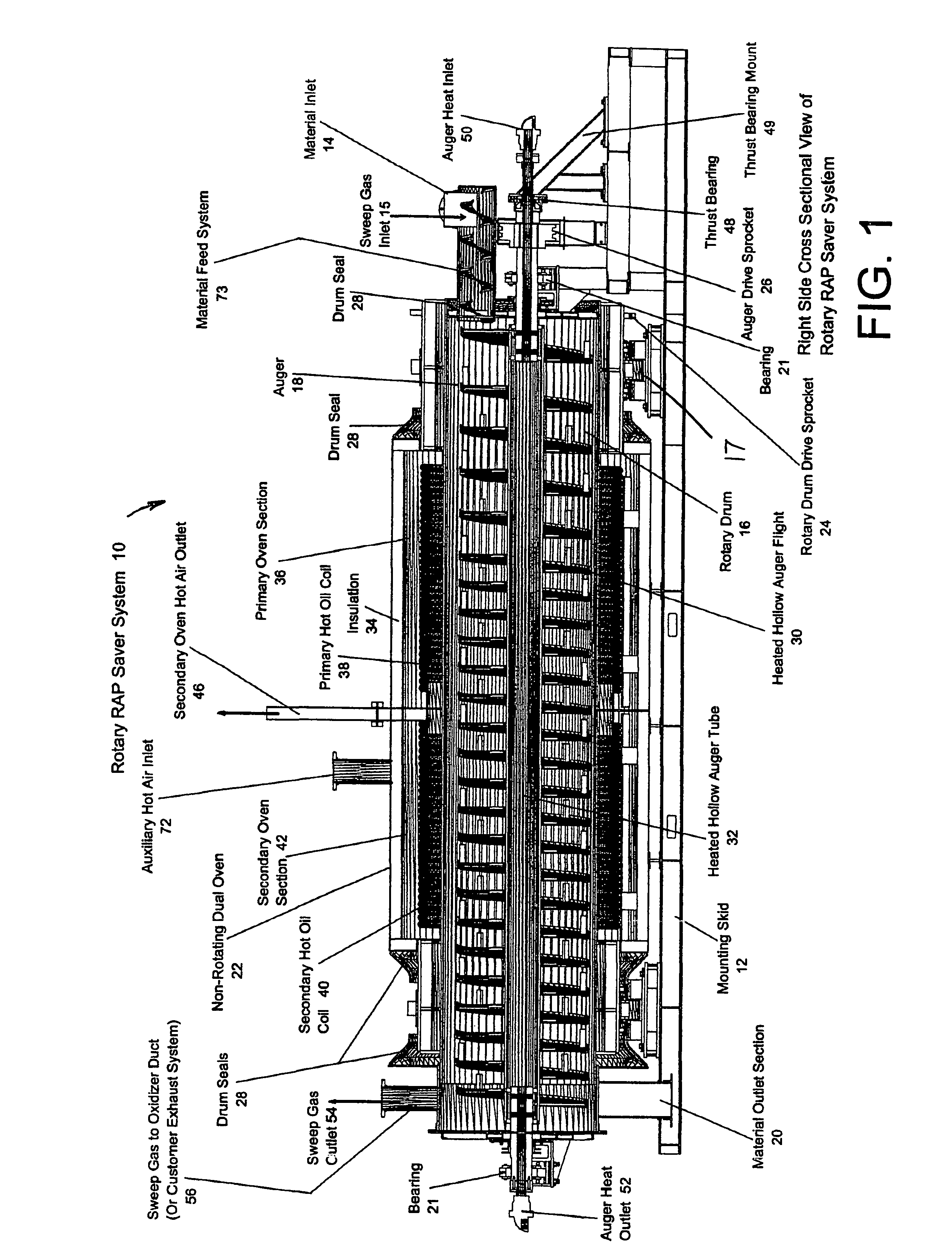
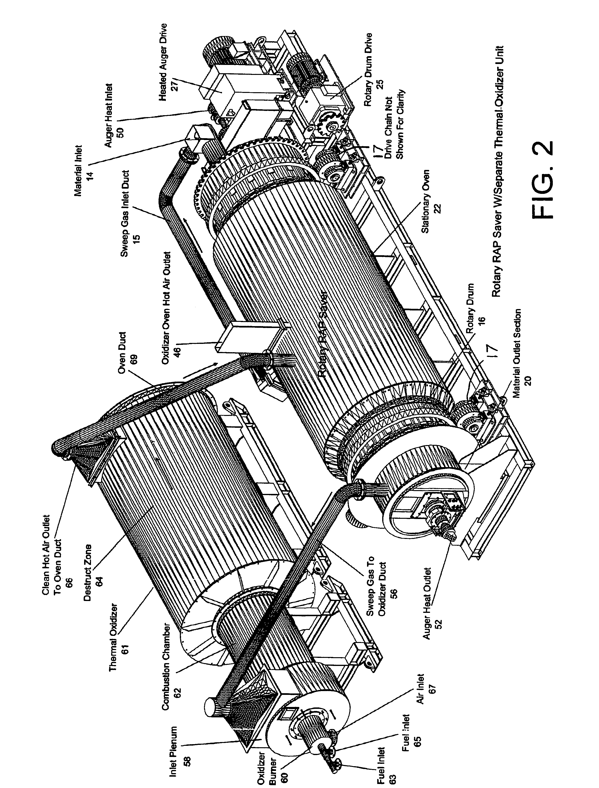
[0037]Referring to FIGS. 1-6, the new Rotary RAP Saver System 10 is skid mounted 12 for ease of installation and is fully operational while mounted on the skid structure 12. The skid arrangement also lends itself to mobilization. The unit modules can be simply mounted on flat bed trailers to travel to new locations. Various different types of feeder systems are available for charging the material into the unit, such as conveyors, drag slats, bucket elevators, vibratory feeders, elevated silos, etc. The raw material is fed into the rotary drum inlet 14 at a pre-qualified and controlled amount or tonnage rate. Different feed mechanisms may be used, such as an inclined chute, breeching with rotating inlet collar, slinger conveyor, screw auger conveyor, among others, whichever is most convenient for the particular type of material. The rotary drum 16 and auger 18 rotate in the same direction. The material inlet 14, material outlet 20, and oven 22 are stationary. The rotary drum 16 is su...


PUM

PropertyMeasurementUnit
temperatureaaaaaaaaaa
temperaturesaaaaaaaaaa

Abstract

A Rotary thermal processor for particulate materials has a rotating drum and a rotating hollow auger. A stationary cylindrical oven with stationary coils surrounds the rotating drum. Hot gas heats a first part of the oven, coil and drum. A rotating hollow auger is heated with hot fluid from the coils. Oven exhaust sweeps evaporated and volatized components of the treated materials to separators and a thermal oxidizer. Cleaned gas from the thermal oxidizer heats a second part of the oven coil and drum and exits a stack. The rotating drum and auger lifts and turns the treated material as it is advanced by the auger.

Description

FIELD OF THE INVENTION[0001]The present invention relates to the thermal processing and restoration of both used and new materials including waste products.SUMMARY OF THE INVENTION[0002]Current technologies, machinery and systems have been invented, and patents applied for that exist for the purpose of heating materials via conduction while controlling the atmosphere within the heating vessel, especially oxygen (O2) content. Heat transfer fluids such as chemicals, thermal oils, and salts, as well as heated exhaust gasses and hot air are heated via a fired heat exchanger, gasification process or oil heater and are then pumped through hollow cavities in screw augers, hollow troughs, jackets, pipes, coils and other heat exchange devices to allow a slow gradual elevation of product temperature and moisture removal.[0003]Two of these devices are currently known as RAP Saver Systems, and as Tar Sands and Oil Shale Volatilizer (TSV) Systems, which are described in patent application Ser. N...

Claims


Application Information

Patent Timeline
Patent Type & Authority Patents(United States)
IPC IPC(8): B28C5/46B28C9/00
CPCE01C19/1031E01C19/1036F27B7/18F27B7/34F27D3/08F27D17/004
Inventor COLLETTE, JERRY R.KELM, WARREN E.
Owner COLLETTE JERRY R
Why Eureka
Try Eureka