Scannerless laser range imaging using loss modulation

a laser range imaging and loss modulation technology, applied in the field of laser range imaging apparatus, can solve the problems of reducing the resolution, affecting the eye safety of people in the field of view, and affecting the accuracy of the image intensifier tube,

Active Publication Date: 2011-08-09
NAT TECH & ENG SOLUTIONS OF SANDIA LLC
View PDF14 Cites 42 Cited by
  • Summary
  • Abstract
  • Description
  • Claims
  • Application Information

AI Technical Summary

Benefits of technology

[0010]The present invention also relates to a scannerless 3-D imaging apparatus to which comprises a continuously-emitting light source which is amplitude modulated in response to a sinusoidal modulation signal at a frequency f0 to provide a non-scanned illumination of the field of view for a period of time; a plurality of loss modulators which are each modulated at the same frequency f0 with a different phase delay δi with respect to the sinusoidal modulation signal, with each loss modulator being adapted to receive a portion of backscattered light from the target and to pro...

Problems solved by technology

The image intensifier tube limits operation of these systems to the visible region and wavelengths below about one micron so that the prior scannerless laser ranging systems are generally not eye-safe for people in the field of view.
Additionally, the image intensifier tube in these systems has a poor resolution of target features; and...

Method used


Image

  • Scannerless laser range imaging using loss modulation
  • Scannerless laser range imaging using loss modulation
  • Scannerless laser range imaging using loss modulation

Examples


Embodiment Construction

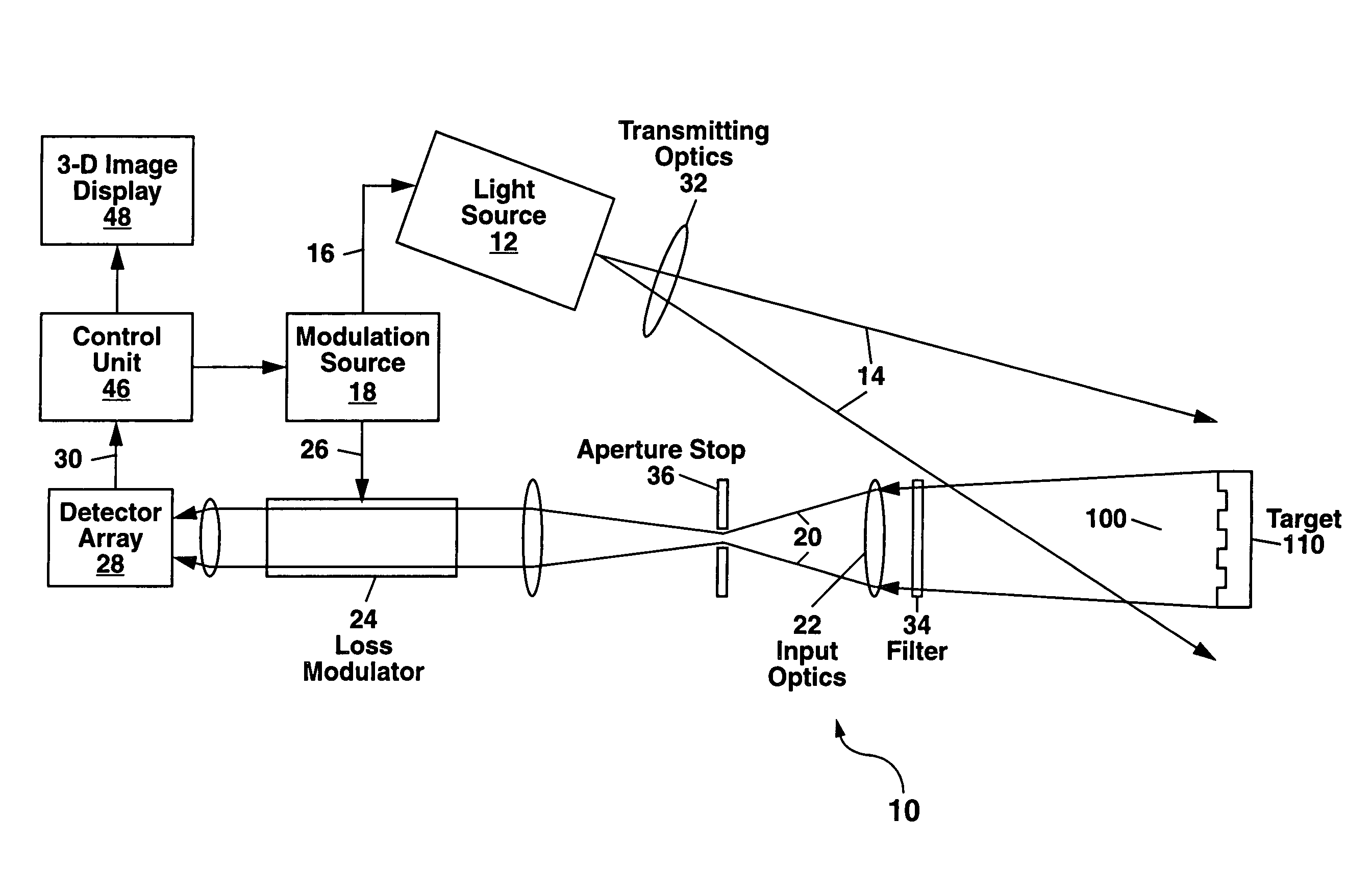
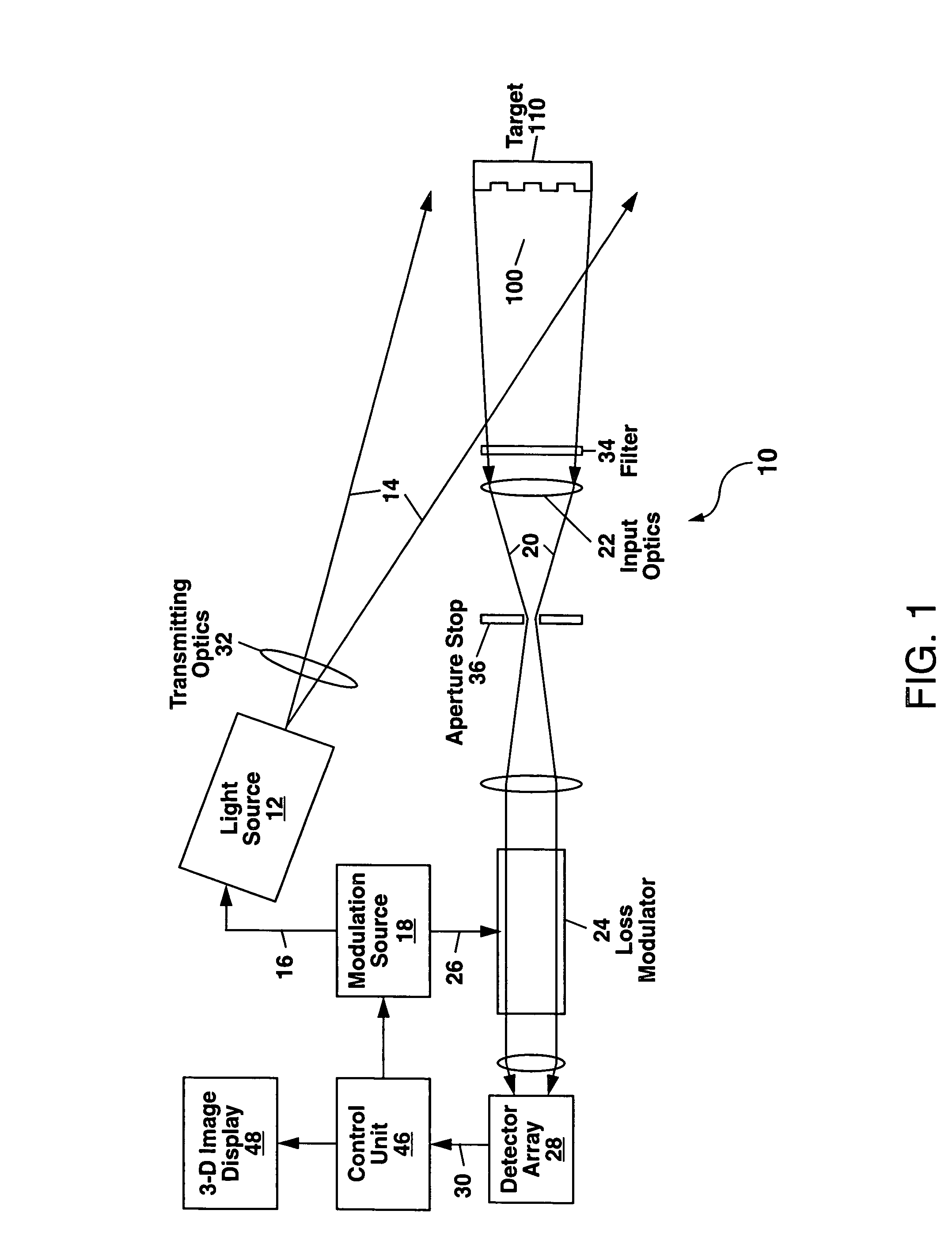
[0018]Referring to FIG. 1, there is shown a first example of the scannerless 3-D imaging apparatus 10 of the present invention. The apparatus 10 comprises a continuously-emitting (also termed continuous-wave or cw) light source 12 which emits a light beam 14 to provide a non-scanned illumination of a field of view 100.

[0019]The terms “continuously-emitting,”“continuous-wave” and “cw” as used herein refer to a light source 12 which emits light over a time scale which is measured in units of microseconds to seconds or longer, and is to be distinguished from a pulsed light source which emits light in pulses with the duration of each light pulse being much smaller than one microsecond, and generally on the order of ten nanoseconds or less. A “continuously-emitting” light source 12 as this term is used herein can also refer to a light source 12 in which the emitted light is modulated at a frequency fo with each modulation cycle of the emitted light having substantially the same peak ampl...


PUM


Abstract

A scannerless 3-D imaging apparatus is disclosed which utilizes an amplitude modulated cw light source to illuminate a field of view containing a target of interest. Backscattered light from the target is passed through one or more loss modulators which are modulated at the same frequency as the light source, but with a phase delay δ which can be fixed or variable. The backscattered light is demodulated by the loss modulator and detected with a CCD, CMOS or focal plane array (FPA) detector to construct a 3-D image of the target. The scannerless 3-D imaging apparatus, which can operate in the eye-safe wavelength region 1.4-1.7 μm and which can be constructed as a flash LADAR, has applications for vehicle collision avoidance, autonomous rendezvous and docking, robotic vision, industrial inspection and measurement, 3-D cameras, and facial recognition.

Description

GOVERNMENT RIGHTS[0001]This invention was made with Government support under Contract No. DE-AC04-94AL85000 awarded by the U.S. Department of Energy. The Government has certain rights in the invention.FIELD OF THE INVENTION[0002]The present invention relates in general to laser ranging and detection (ladar), and in particular to a scannerless laser range imaging apparatus having a receiver which utilizes loss modulation to construct a three-dimensional (3-D) image of a target within a field of view of the apparatus.BACKGROUND OF THE INVENTION[0003]Previous scannerless laser ranging systems which operate with an amplitude-modulated continuous-wave (CW) laser source have generally utilized an image intensifier tube in the receiver (see e.g. U.S. Pat. Nos. 4,935,616 and 6,088,086 which are incorporated herein by reference). The image intensifier tube limits operation of these systems to the visible region and wavelengths below about one micron so that the prior scannerless laser rangin...

Claims


Application Information

Patent Timeline
IPC IPC(8): G01C3/08
CPCG01S17/36G01S17/89G01S7/4912G01S7/4816G01S17/894
Inventor SANDUSKY, JOHN V.
Owner NAT TECH & ENG SOLUTIONS OF SANDIA LLC
Why Eureka
Try Eureka