Automatic retractable floor system for a rotating gantry

a technology of rotating gantry and automatic retractable floor, which is applied in the direction of washstands, furniture parts, and therapy, etc., can solve the problems of affecting the rotation of the gantry about the patient, the inability to provide access to the patient table, and the damage to healthy cells within the patient's body, so as to achieve high functional

Inactive Publication Date: 2011-08-16
INDIANA UNIV RES & TECH CORP
View PDF13 Cites 49 Cited by
  • Summary
  • Abstract
  • Description
  • Claims
  • Application Information

AI Technical Summary

Benefits of technology

[0010]In order to address the need for a highly functional floor around the patient table, the present invention contemplates a floor assembly that includes floor segments or panels that extend to mate with the fixed floor of the treatment room and that retract to allow passage of the nozzle as the gantry rotates. In accordance with certain aspects of the invention, the movable panels are capable of supporting the weight of one, and preferably two, average sized adults when fully extended. The floor assembly permits rotation of the gantry from −185° to the +185° about the patient by retracting the movable panels. The floor panels mechanically latch to the fixed treatment room floor when fully extended and cannot be unintentionally released by personnel or equipment moving across the floor panels.
[0013]It is one object to provide a floor assembly that can be used with a rotating gantry and radiation nozzle system at a radiation treatment facility. It is a further object that the floor assembly be controllable to ensure adherence to certain safety protocols while also ensuring that no collisions will occur between the nozzle and the floor assembly as the gantry rotates.

Problems solved by technology

In proton beam therapy, the patient must be accurately positioned with respect to the one or more beams so that the stream irradiates only the desired target region, otherwise the stream may damage healthy cells within the patient's body.
Together these systems form a highly complex collection of hardware and software components.
In particular, any platform or floor providing access to the patient table will necessarily interfere with the necessary rotation of the gantry about eh patient.

Method used


Image

  • Automatic retractable floor system for a rotating gantry
  • Automatic retractable floor system for a rotating gantry
  • Automatic retractable floor system for a rotating gantry

Examples


Embodiment Construction

[0062]For the purposes of promoting an understanding of the principles of the invention, reference will now be made to the embodiments illustrated in the drawings and described in the following written specification. It is understood that no limitation to the scope of the invention is thereby intended. It is further understood that the present invention includes any alterations and modifications to the illustrated embodiments and includes further applications of the principles of the invention as would normally occur to one skilled in the art to which this invention pertains.

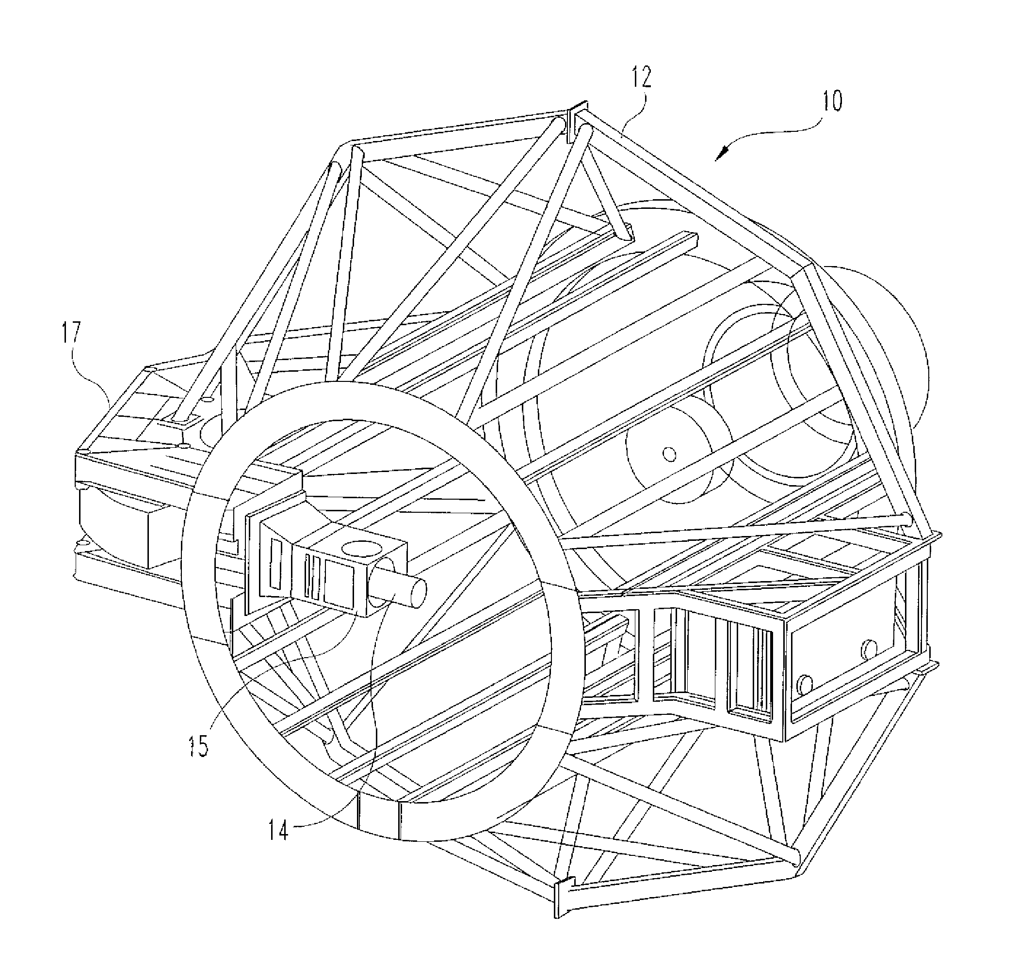
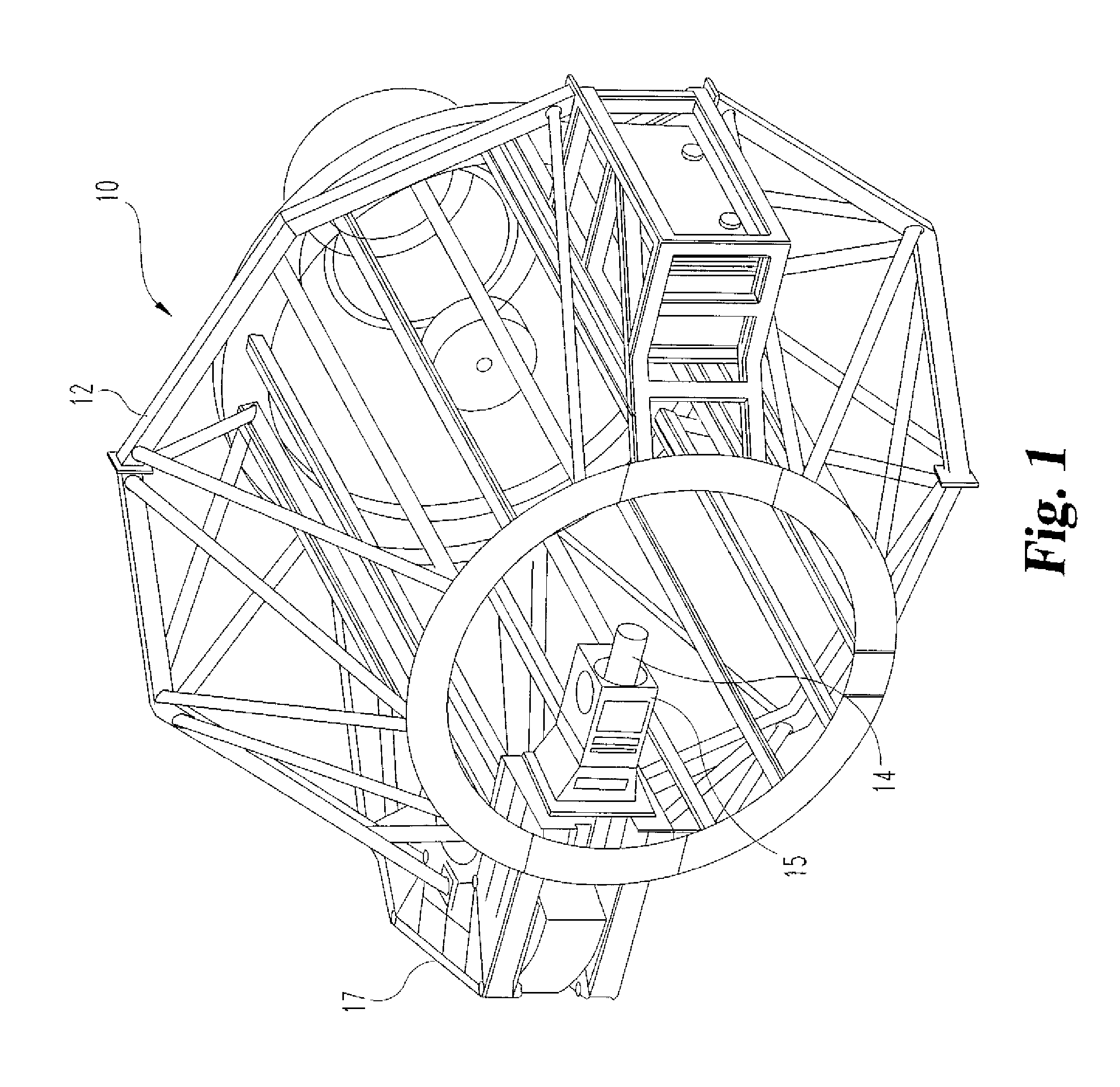
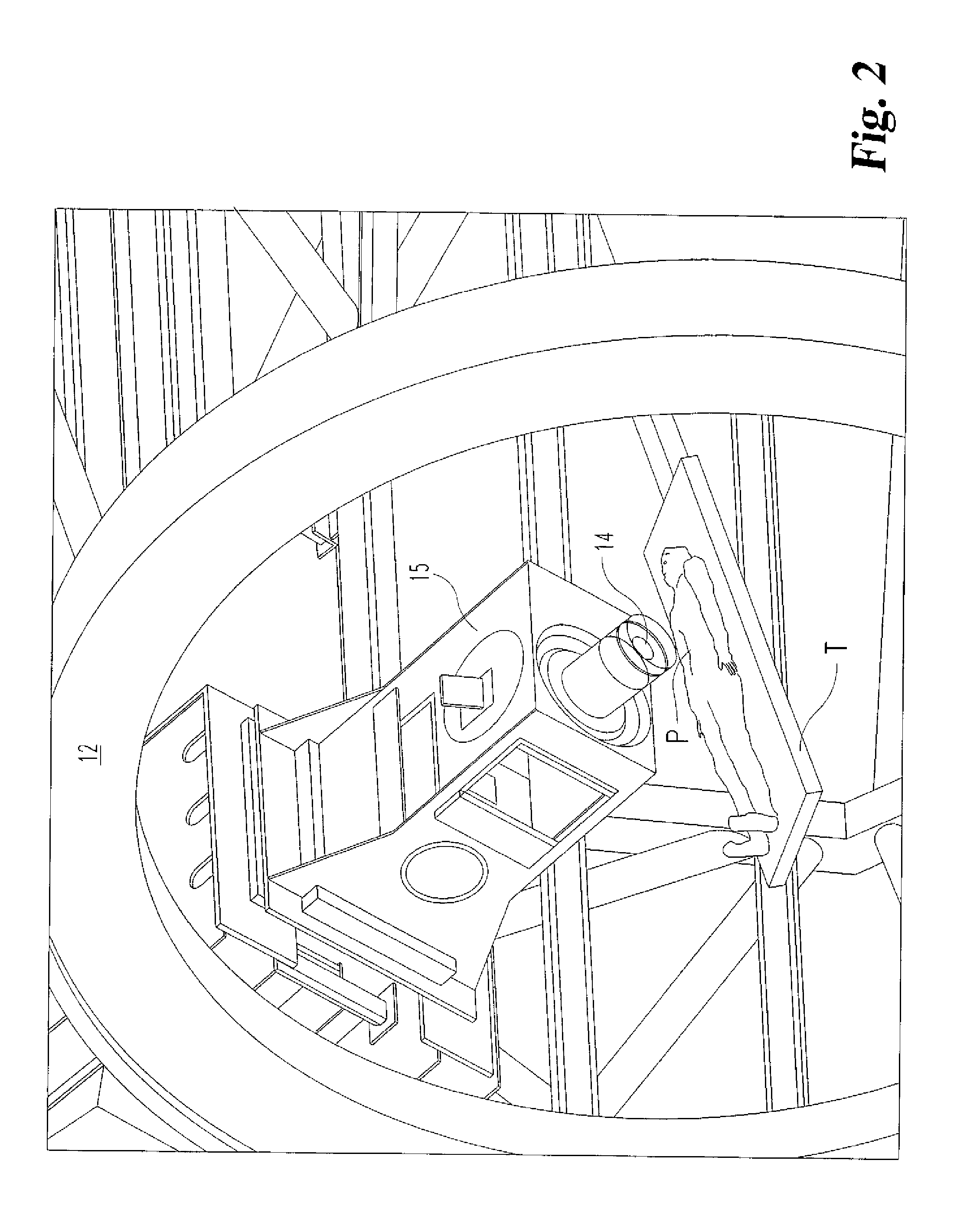
[0063]As shown in FIGS. 3-4, the present invention contemplates a movable floor system 20 that is supported on a carriage assembly 22. The carriage assembly is supported relative to the gantry 12 so that the floor system 20 maintains its neutral horizontal position even as the gantry is rotated. The floor system 20 includes an extendable panel assembly 24 that controls the extension and retraction of various mov...


PUM


Abstract

A movable floor system for use with a rotating gantry in a radiation treatment facility is provided that comprises a carriage assembly slidably supported within the gantry to maintain a substantially constant orientation while the gantry is rotating. An extendable / retractable panel assembly is supported on the carriage assembly that includes a plurality of non-movable floor panels and a like plurality of movable floor panels slidably mounted over corresponding ones of the non-movable panels. The movable panels are sized to span a distance between the carriage assembly and a fixed floor of the treatment room. Each of the movable panels has a platform surface for supporting a person for access to and from the patient table situated within the gantry. A control system coordinates the extension and retraction of the movable floor panels to prevent collisions with the radiation nozzle as it rotates during the patient treatment.

Description

REFERENCE TO RELATED APPLICATION[0001]This application claims priority to co-pending U.S. Provisional application No. 60 / 643,951, filed on Jan. 14, 2005, the disclosure of which is incorporated herein by reference.BACKGROUND OF THE INVENTION[0002]1. Field of the Invention[0003]The present invention relates to particle radiation therapy systems and, in particular, to the access floor surrounding a patient table within a rotating gantry system.[0004]2. Description of the Related Art[0005]Particle radiation therapy involves coordinating complex systems and devices to enable targeting of specific cancerous regions of a patient. In particular, proton beam therapy utilizes one or more precisely aligned particle streams to irradiate cancer or tumor cells. The energized protons disrupt targeted cells or tissue so as to effectively halt the progression of the disease. In proton beam therapy, the patient must be accurately positioned with respect to the one or more beams so that the stream ir...

Claims


Application Information

Patent Timeline
Patent Type & Authority Patents(United States)
IPC IPC(8): A47B91/00
CPCA61N5/10A61N5/1081A61N2005/1087
Inventor SLOAN, TERRYSTARKS, EARL W.
Owner INDIANA UNIV RES & TECH CORP
Why Eureka
Try Eureka