Micro-bubble generator, vortex breakdown nozzle for micro-bubble generator, vane swirler for micro-bubble generator, micro-bubble generating method, and micro-bubble applying device

a micro-bubble generator and generator technology, applied in the direction of combustible gas purification/modification, lighting and heating apparatus, separation processes, etc., can solve the problems of inability to accurately set, the above-conventional micro-bubble generator cannot be easily designed small or large, and the connection directly to the existing apparatus cannot be accurate. , to achieve the effect of effective use of porous materials, increase the area of contact between a gas and liquid, increase the time of contact between gas

Inactive Publication Date: 2011-08-16
UNIV OF TSUKUBA
View PDF15 Cites 12 Cited by
  • Summary
  • Abstract
  • Description
  • Claims
  • Application Information

AI Technical Summary

Benefits of technology

[0016]The liquid flow may basically be swirled in any one of well-known manners. However, it should preferably be swirled with the use of a swirling-flow generating vane type nozzle coupled coaxially to the vortex breakdown nozzle. In this case, the swirling flow is produced by supplying the liquid to the inlet of the swirling-flow generating vane type nozzle. Typically, the swirling-flow generating vane type nozzle includes a vane swirler accommodated in a cylindrical pipe, for example (or the outer surfaces of such vane swirler are enclosed in a pipe). Typically, the vane swirler includes a cylindrical body of which one end portion is formed streamlined (typically like a body of revolution (hemispheric, for example) taking the center axis of the cylindrical body as the axis of revolution) and a plurality of vanes provided on the outer surface of the cylindrical body longitudinally of the latter to have their rear portions curved. A gas jet orifice is formed in the other end face thereof. Typically, the vane swirler has a gas inlet formed in the outer surface of the cylindrical body and the gas jet orifice formed at the other end of the cylindrical body, and the gas inlet and jet orifice communicate with each other via a channel formed in the cylindrical body. The pipe accommodating the vane swirler may be formed uniform in diameter. However, for a higher efficiency of conversion, by the swirling-flow generating vane type nozzle, of a liquid supplied from one end of the pipe into a swirling flow as well as for reduction of energy loss of the liquid by lessening the influence of the flow constricted by the swirling-flow generating vane type nozzle, the pipe should preferably include a first section and a second section thicker than the first section and in which the vane swirler is accommodated.
[0017]Typically, the micro-bubble generator further includes a gas feeding unit that feeds a gas to a gas inlet of the swirling fluid generating vane assembly. Preferably, the gas feeding unit should have a breather controllable in sectional area, and be designed so that the rate at which the gas fed to the gas inlet of the swirling-flow generating vane nozzle is adjusted by controlling the sectional area of the breather. Typically, the breather of the gas feeding unit and gas inlet of the vane swirler are connected to each other by a gas supply tube via which the gas is fed from the breather of the gas feeding unit to the gas inlet of the vane swirler. Typically, the sectional area of the breather is controlled based on a result of detection of a pressure in the vortex breakdown section or on the combination of this result of detection and a result of detection of a pressure outside the vortex breakdown section. It is thus possible to feed the gas to the swirling flow automatically.
[0028]The present invention has the advantages as will be described below. According to the present invention, micro bubbles can easily be generated just by supplying the vortex breakdown nozzle with a swirling liquid flow produced by the swirling-flow generating vane nozzle etc. and having a gas introduced to the center thereof. The components of the micro-bubble generator, such as the vortex breakdown nozzle, swirling-flow generating vane nozzle, etc. may be disposed linearly so that the micro-bubble generator can easily be designed small or large for easy direct connection of the micro-bubbler generator to an existing apparatus using the micro bubbles. For example, the micro-bubble generator thus designed small can easily be assembled in a part of an apparatus. Also, the large micro-bubble generator designed large will advantageously be employable in a large-scale project such as purification of an expanse of water, for example.
[0030]Also, since the groove depth and blow-out angle of the swirling-flow generating vane nozzle can be adjusted correspondingly to the performance of a pump used for supply of a liquid, the micro-bubble generator can easily be designed optimally.
[0031]Micro bubbles are helpful for the nature-symbiosis technology adopted in the water purification, recycling of construction sludge, etc. Having a unique physico-chemical quality, the micro bubbles are utilizable in various fields of industry and very important for the industries. Porosity contributes to weight reduction of a material, and the micro bubbles are effectively utilizable to produce porous materials. More specifically, the area of contact between a gas and liquid can be increased by injecting the gas in the form of microbubbles into the liquid, and also the time of contact between the gas and liquid can be increased by delaying floating of the micro bubbles to increase solution of the gas into the liquid. Suspended solids in the liquid can effectively be removed owing to the effect of adsorption / condensation and flotation of the micro bubbles. The peeling effect of the micro bubbles and energy developed at breakdown of the micro bubbles can effectively be used in cleaning. Also, the micro bubbles are effectively usable for development of new techniques in the field of earthwork, such as prevention of the liquefaction of sand-layer ground etc.
[0032]The micro bubbles generated by the above micro-bubble generator and micro bubbles-applied apparatus can effectively be used in various fields of industry such as various types of purification of an expanse of water (water purification of lakes, rivers, reservoirs, etc.), tideland regeneration, cultivation of oysters and scallops, reduction of resistance to marine vessels, descaling of lead pipes, ultrasonic washing, fields of agriculture, forestry and fisheries, fields of medicine, field of sanitation, etc.

Problems solved by technology

Being so extremely small, the micro bubbles will adsorb fine contaminants and make them rise to the water surface.
However, the above conventional micro-bubble generator cannot easily be designed small or large and connected directly to an existing apparatus using the micro bubbles since the components thereof are not disposed linearly.
The size of air bubbles generated depends upon the amount of the gas introduced into the liquid but cannot accurately set since the feed rate has to be adjusted intuitively.

Method used


Image

  • Micro-bubble generator, vortex breakdown nozzle for micro-bubble generator, vane swirler for micro-bubble generator, micro-bubble generating method, and micro-bubble applying device
  • Micro-bubble generator, vortex breakdown nozzle for micro-bubble generator, vane swirler for micro-bubble generator, micro-bubble generating method, and micro-bubble applying device
  • Micro-bubble generator, vortex breakdown nozzle for micro-bubble generator, vane swirler for micro-bubble generator, micro-bubble generating method, and micro-bubble applying device

Examples


first embodiment

[0061]First, there will be explained the micro-bubble generator as the present invention.

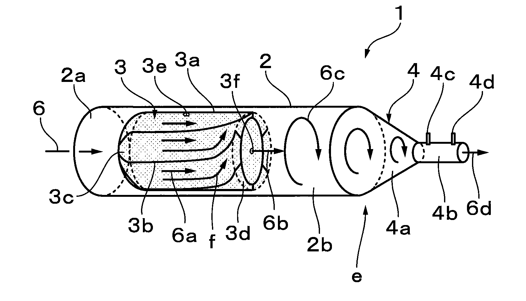
[0062]To generate microbubbles, this micro-bubble generator has disposed serially therein a turbine vane type nozzle that forms a strong swirling flow from a liquid such as water flowing through a pipe by closing a central portion of the pipe to increase the circumferential flow velocity of the liquid, and a vortex breakdown nozzle that changes, into a small flow, a flow of the liquid superior in circulation to the main flow. Also, to adjust the diameter of each micro bubble, a pressure difference in the vortex breakdown nozzle is detected to automatically adjust the rate at which a gas is fed into the swirling flow so that the vortex breakdown will take place stably in the vortex breakdown nozzle.

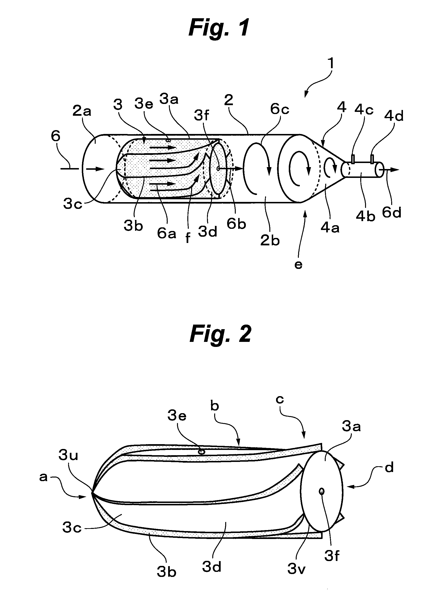
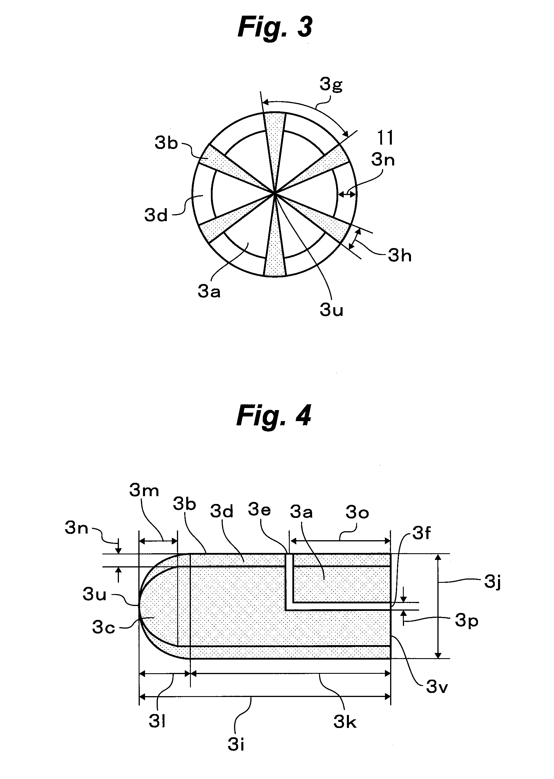
[0063]FIG. 1 shows a main unit of the micro-bubble generator, FIG. 2 to 4 show the turbine vane type nozzle in the micro-bubble generator, FIG. 5 is a development elevation of one of the vanes of the t...

second embodiment

[0137]Next, there will be explained the micro-bubble generator as the present invention.

[0138]In the micro-bubble generator 1, the vortex breakdown section 4b of the vortex breakdown nozzle 4 has provided at the end thereof an inverse-tapered (or divergent) section 4h that provides a wide outlet as shown in FIG. 20. More specifically, in the vertex breakdown nozzle 4 of the micro-bubble generator 1 as the first example of the first embodiment, the angle 4i of the outlet end of the vortex breakdown section 4b is 0 deg. while the vortex breakdown nozzle 4 of the micro-bubble generator 1 as the second example of the first embodiment has the inverse-tapered section 4h that provides a sufficiently wide outlet having the angle (taper angle) 4i. More specifically, the angle 4i is on the order of 60 or 80 deg., for example, to which however the present invention is not limited.

[0139]In the vortex breakdown nozzle 4 in the first embodiment of the present invention, the gas column 6b develope...

third embodiment

[0148]Next, there will be explained the micro-bubble generator as the present invention.

[0149]As shown in FIG. 23, the micro-bubble generator 1 is different from the micro-bubble generator 1 as the first embodiment of the present invention in the respect of the connection between the turbine vane type nozzle 3 and vortex breakdown nozzle 4 and the gas feeding unit 5. More specifically, the micro-bubble generator 1 is characterized in that the gas feeding is automated by connecting the breather 5f of the gas feeding unit 5 and gas inlet 3e of the turbine vane type nozzle 3 to each other, high-pressure section 5j of the gas feeding unit 5 and pressure sensor 4c at the inlet of the vortex breakdown section 4b of the vortex breakdown nozzle 4 to each other, and the low-pressure section 5k of the gas feeding unit 5 and pressure sensor 4d provided outside the vortex breakdown nozzle 4 to each other. Thus, the pressure sensor 4c detects the pressure of the gas column 6b passing through the...


PUM

PropertyMeasurementUnit
angle θ0aaaaaaaaaa
diameteraaaaaaaaaa
vane angleaaaaaaaaaa

Abstract

There is provided a micro-bubble generator including a swirling-flow generating vane nozzle and vortex breakdown nozzle connected coaxially to each other. The swirling flow generating vane nozzle produces a swirling flow of a liquid having a gas introduced to the center thereof from a gas feeding unit. The swirling flow is supplied to a flow constricting section included in the vortex breakdown nozzle to provide micro bubbles from a vortex breakdown section also included in the vortex breakdown nozzle.

Description

CROSS REFERENCE TO RELATED APPLICATION[0001]The present application claims priority benefits under 35 U.S.C. §371 to International Patent Application No. PCT / JP2005 / 021502, entitled “Micro-Bubble Generator, Vortex Breakdown Nozzle for Micro-Bubble Generator, Vane Swirler for Micro-Bubble Generator, Micro-Bubble Generating Method, and Micro-Bubble Applying Device,” filed Nov. 17, 2005, and claims priority to Japanese Patent Application No. 005813 / 2005, filed Jan. 13, 2005, and Japanese Patent Application No. 143682 / 2005, filed May 17, 2005, the entire contents of all of which are incorporated by reference in their entirety.TECHNICAL FIELD[0002]The present invention relates to a micro-bubble generator, vortex breakdown nozzle for the micro-bubble generator, vane swirler for the micro-bubble generator, micro-bubble generating method and a micro-bubble applying device, which are suitably applied in, for example, water purification with micro bubbles.BACKGROUND ART[0003]The micro bubbles...

Claims


Application Information

Patent Timeline
Patent Type & Authority Patents(United States)
IPC IPC(8): B01F3/04B01F5/02
CPCA01K63/042B01F3/0446B01F5/0646B01F5/0651B01F5/0665B01F5/0671C02F1/006B01F2003/04858B01F2003/04865B01F2003/04872B01F2003/04879B01F2003/04886B01F2003/04914B01F2005/0017B01F2215/0052C02F1/72C02F1/78C02F2301/024C02F2301/026B01F23/232B01F23/23761B01F23/23764B01F23/237611B01F23/2373B01F23/237612B01F23/237613B01F2025/913B01F25/4334B01F25/44163B01F25/4413B01F25/433B01F2101/305
Inventor ABE, HARUMICHIMATSUUCHI, KAZUOIIDAKA, MINORU
Owner UNIV OF TSUKUBA
Why Eureka
Try Eureka