Axial plain bearing assembly

a technology of axial bearings and assembly parts, which is applied in the direction of sliding contact bearings, mechanical equipment, machines/engines, etc., can solve the problems of increasing structural parts, assembly costs, and relative high degree of leakage, and achieves the effects of reducing the number of components, high efficiency, and reducing assembly costs

Inactive Publication Date: 2011-08-16
CARL FREUDENBERG KG
View PDF25 Cites 12 Cited by
  • Summary
  • Abstract
  • Description
  • Claims
  • Application Information

AI Technical Summary

Benefits of technology

[0015]The axial plain bearing assembly according to the present invention not only functions as an axial support of the drive shaft that is particularly effective at high to very high rotational speeds, but, at the same time, it provides a highly effective gas-lubricated mechanical face seal in that the assembly a rotary thrust ring of the axial plain bearing assembly has a seal face on an end face thereof opposite to that having a conventional bearing surface. Although the thrust ring takes on the function of a rotary seal ring in a gas-lubricated mechanical face seal, thereby simultaneously resulting in a corresponding saving in number of components, distortion of the thrust ring caused by thermal effects from the side of the axial bearing assembly is prevented in an effective manner. Such distortion would result in a harmful change of the shape of a sealing gap of the mechanical face seal formed during operation. Assembly of the components for axially supporting a shaft, and especially the drive shaft of a compressor, is simplified since there is only a single assembly step for obtaining the two functions of axial support and sealing. If desired, the multi-function thrust ring and the mass ring may be an integral part of a shaft bushing or may be provided pre-assembled thereon. The structure that includes the seal, the bearing and the shaft bushing may be provided as a pre-assembled unit and may be inserted into a boring of a casing, e.g. a compressor casing, which has to be sealed, in an assembly-friendly manner. Part-by-part assembly at the point of use can likewise be affected in problem-free manner. A further advantage arising from the design of the thrust ring as a multi-function component is that the labour intensive grinding processes required for providing the bearing and seal faces on the thrust ring can be carried out, if necessary without re-clamping, on one and the same machine tool.

Problems solved by technology

Hitherto, labyrinth seals or a sealing effect produced by means of piston rings were mostly used, both of which are associated with a relatively high degree of leakage.
The separate structural measures for the sealing and bearing functions involve an increase in the structural parts and assembly costs for fulfilling the functions of supporting and sealing.

Method used


Image

  • Axial plain bearing assembly
  • Axial plain bearing assembly
  • Axial plain bearing assembly

Examples


example

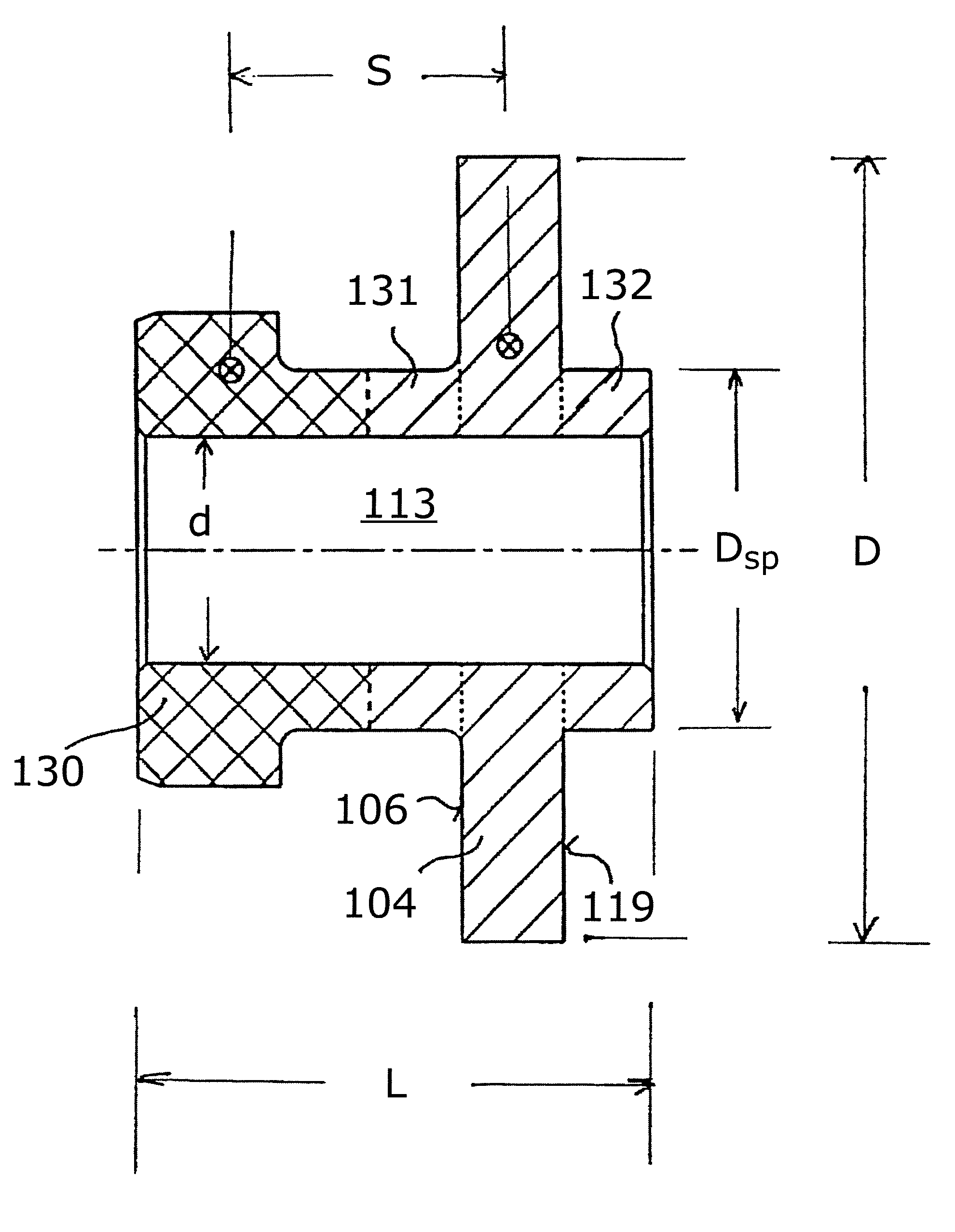
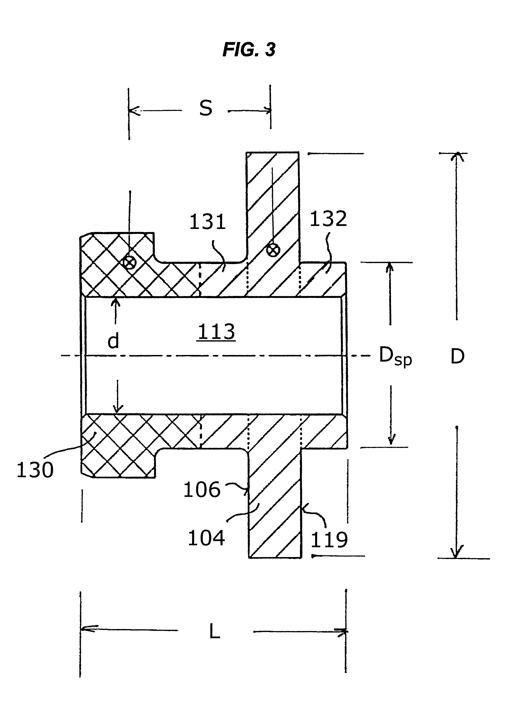
[0043]An axial plain bearing assembly was constructed in accordance with the present invention for use in a charge compressor of an internal combustion engine. The medium to be sealed was air. In the seal face 106 of the thrust ring 104 gas-pumping grooves (e.g., grooves 7) were incorporated and peripherally distributed. Tests showed that substantially full compensation of thermal distortion of the thrust ring 104 within a wide range of rotary speeds of the shaft 2 up to 105 min−1 could be obtained when a bushing 113 made of steel material and having a thrust ring 104, a mass ring 130, and spacer rings 131, 132 as integral parts thereof, was provided, which had the following parameters (also shown in FIG. 3): L=11 mm, D=17 mm, d=5 mm, DSp=8 mm, S=6 mm; mass of mass ring 130: 2.9 gr., mass of thrust ring 104: 3.2 gr., wherein L=overall length of bushing 113, D=outer diameter of thrust ring 104, d=diameter of bore in bushing 113, DSp=outer diameter of spacer rings 131, 132, S=axial di...


PUM


Abstract

An axial plain bearing assembly includes a thrust ring provided for common rotation with a rotary component. The thrust ring has a radial seal face on an end face thereof for co-operating with a radial seal face of a non-rotational seal ring of a gas-lubricated mechanical face seal assembly for sealing said rotary and stationary components against each other. A plurality of peripherally spaced gas-pumping grooves is formed in at least one of the radial seal faces of the thrust and non-rotational seal rings. A mass ring connected with the thrust ring is provided at an axial distance from the thrust ring. The mass ring is configured and adapted to exert a balancing force on the thrust ring under centrifugal forces acting on the mass ring during common rotation of the mass and thrust rings to compensate for thermal distortion of the thrust ring during operation.

Description

CROSS REFERENCE TO RELATED APPLICATIONS[0001]This application is a continuation-in-part of U.S. patent application Ser. No. 10 / 843,630 filed May 12, 2004, which claims priority to German Utility Model Application No. 203 07 447.5, filed May 13, 2003, which are incorporated by reference herein in their entireties.BACKGROUND OF THE INVENTION[0002]1. Field of the Invention[0003]The present invention relates to an axial plain bearing assembly and in particular, to an axial plain bearing assembly suitable for the axial support of the drive shaft of a combustion air-charge compressor for use in internal combustion engines.[0004]2. Background of the Related Art[0005]For the axial support and sealing of the drive shaft of a turbo-mechanically driven centrifugal or screw-type compressor or a turbo compressor having an exhaust-gas driven turbine, the special operating conditions of such aggregates require appropriate attention. For instance the drive shafts generally have a very small diamete...

Claims


Application Information

Patent Timeline
Patent Type & Authority Patents(United States)
IPC IPC(8): F16C33/74F16C33/06
CPCF01D3/04F01D25/168F16C17/04F16C17/22F16C17/24F16C25/04F16C33/107F16J15/3412F16J15/348F05D2220/40F16C2360/24
Inventor SIMON, CLEMENSFEIGL, PETER
Owner CARL FREUDENBERG KG
Why Eureka
Try Eureka