
Endoscope system comprising endoscope to which medical instrument is attached

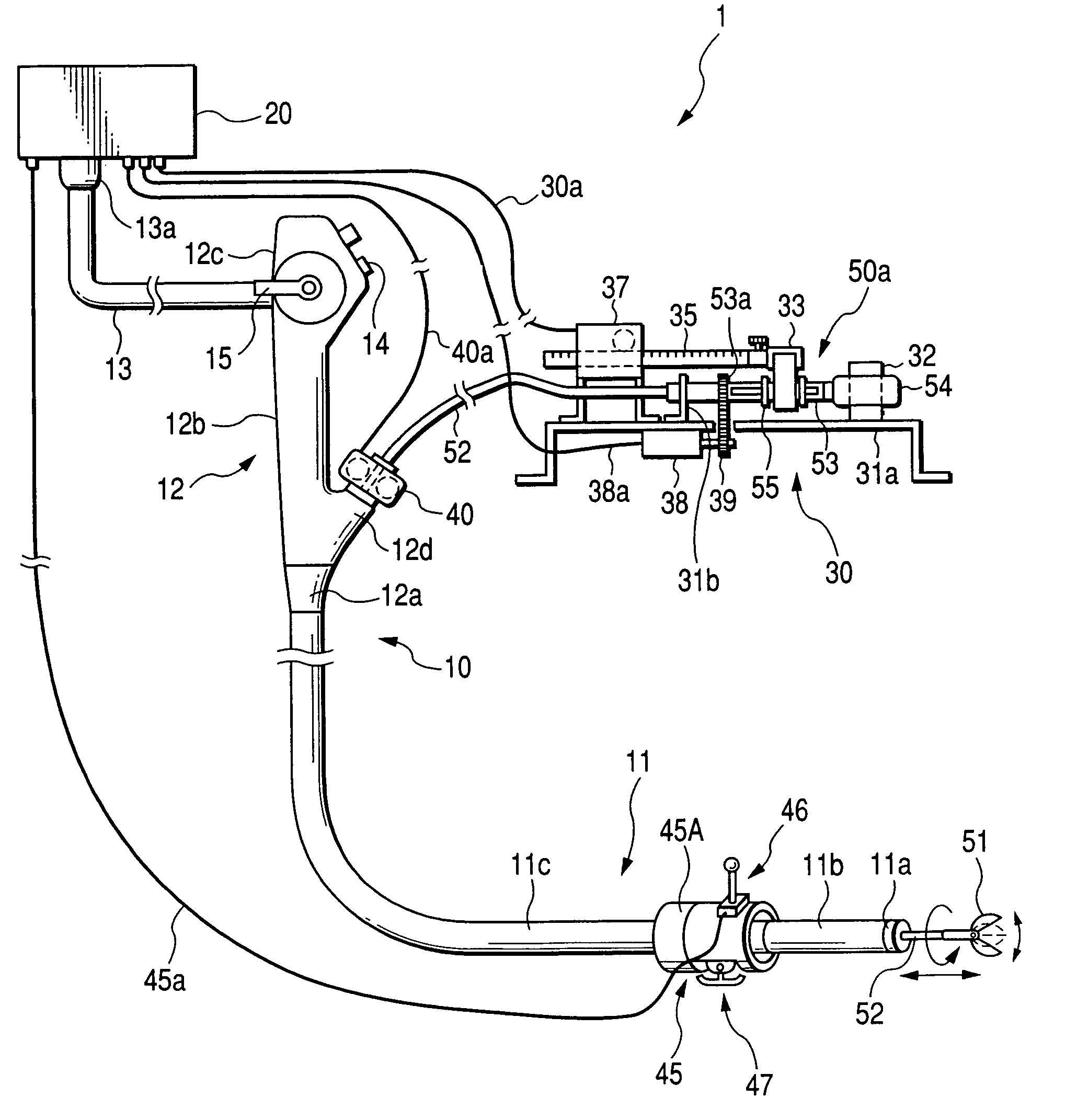
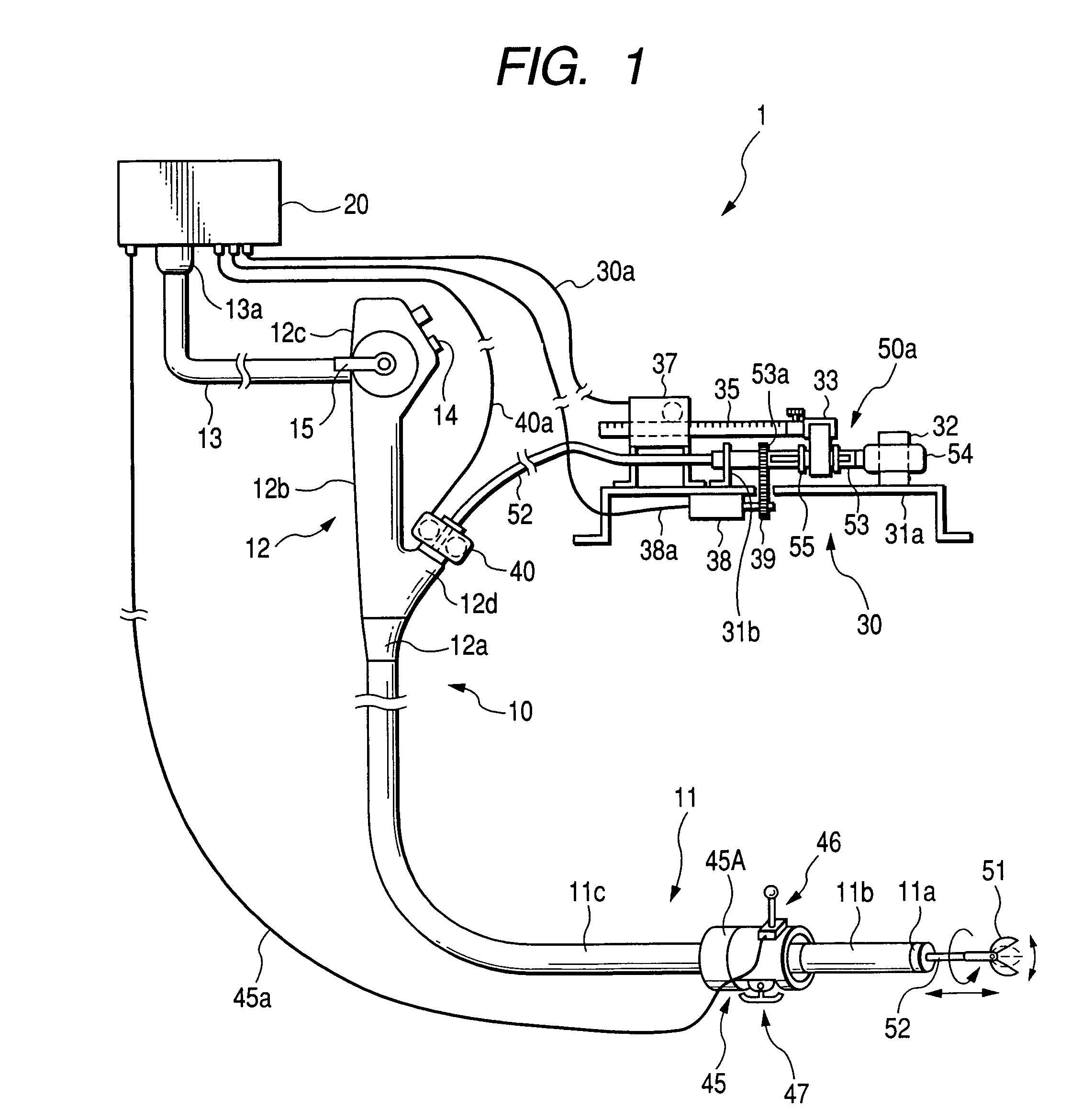
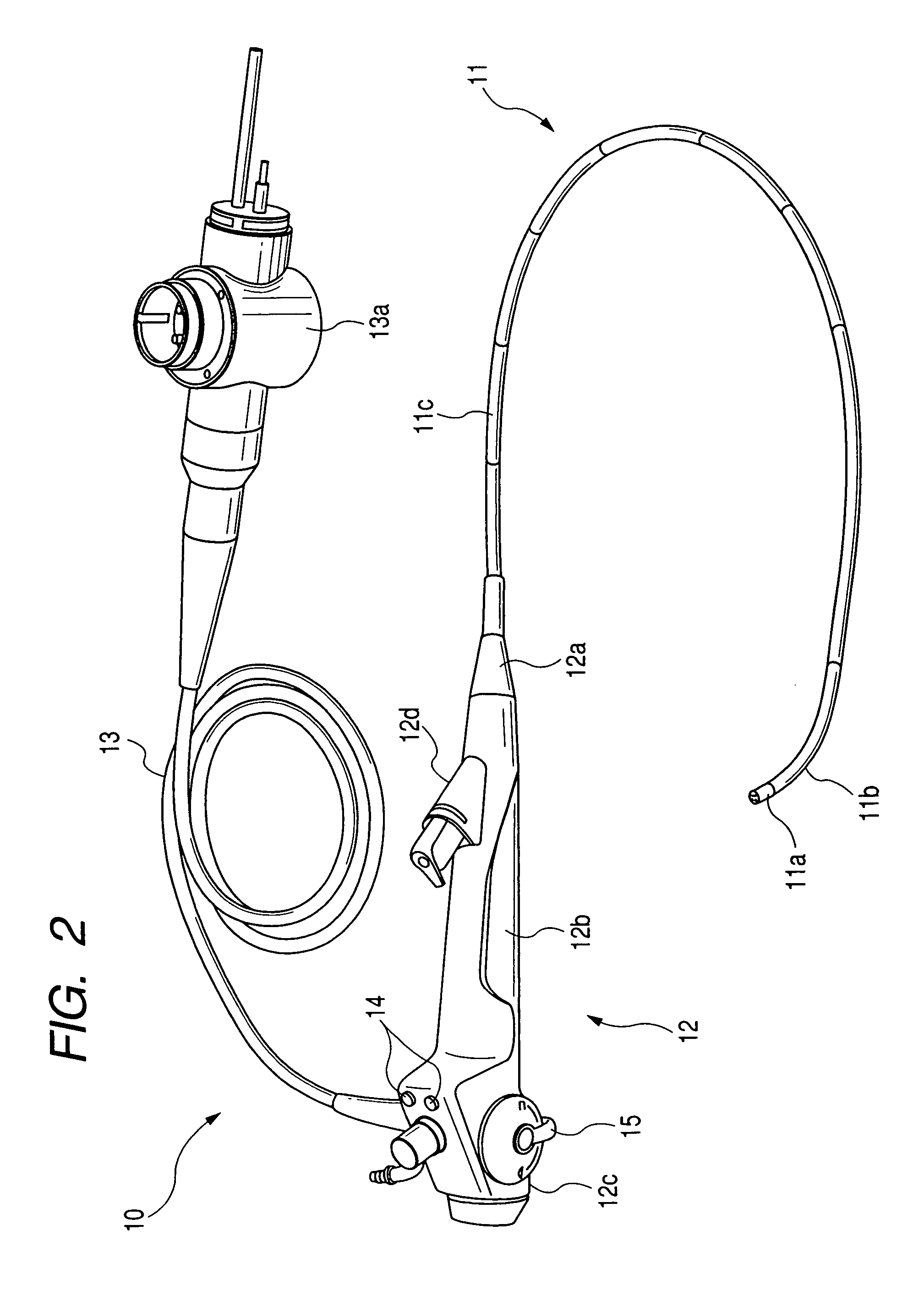
a technology of endoscope and endoscope, which is applied in the field of endoscope system, can solve the problems of increasing the power required for inserting and pulling out therapeutic instruments, difficult operation of various therapeutic instruments, and difficulty in achieving desired inserting and pulling out operations, etc., and achieves the effect of raising the operationality

Active Publication Date: 2011-08-16
OLYMPUS CORP
View PDF15 Cites 50 Cited by
  • Summary
  • Abstract
  • Description
  • Claims
  • Application Information

AI Technical Summary

Benefits of technology

The system enhances operational efficiency by maintaining consistent speed and reducing operator effort, ensuring smooth insertion and retrieval of therapeutic instruments regardless of the bend angle and channel configuration, improving the overall usability of the endoscope.

Problems solved by technology

Thus the insertion becomes a troublesome operation for the operator, making operating various therapeutic instruments difficult.
In such situations, the larger a curbed angle of the bendable section becomes, the larger the power required for inserting and pulling out the therapeutic instrument.
However, the configurations shown by the foregoing two patent publications have a difficulty in a case where the power is set to a value necessary for smooth inserting and pulling-out operations of a therapeutic instrument into and from the bendable section bent at a maximum curve angle thereof.
In this case, the bendable section is in a straight (no curved) or in a less curved angle state, the therapeutic instrument is forced to be inserted and pulled out by power larger than an optimally necessary amount, thus making desired inserting and pulling-out operations difficult.
Thus, when the bendable section of an endoscope is bent, a small amount of play between the wall of the therapeutic channel and the sheath of the therapeutic instrument may cause a delay in the response of the inserting and pulling-out operations of the therapeutic instrument.
Additionally, in the case of the configuration shown by the later patent publication, when the bendable section is bent, the similar difficulty to the inserting and pulling-out operations may be caused in a force to open and close such therapeutic instruments as clamping forceps as well as an amount to be open and closed thereof.

Method used


Image

  • Endoscope system comprising endoscope to which medical instrument is attached
  • Endoscope system comprising endoscope to which medical instrument is attached
  • Endoscope system comprising endoscope to which medical instrument is attached

Examples


first control example

[0103]Referring to FIGS. 13-17, a first control example based on the first program shown in FIG. 13 will now be described, in which the sheath 52 of the therapeutic instrument 50 is inserted and pulled out in response to commands from the instrument processor 20d.

[0104]In response to operator's inserting or pulling-out operation for the therapeutic instrument 50 at the manipulating unit 45, the instrument processor 20d receives a command signal for the inserting or pulling-out operation from the unit 45 (FIG. 13, Step S11). The instrument processor 20d uses the received command signal to drive the instrument conveying unit 40 (Step S12), whereby the sheath 52 (together with the operating wire 52a) of the instrument 50 can be inserted or pulled out in or from the therapeutic channel 11CH.

[0105]Then the instrument processor 20d detects a bent state of the bendable section 11b of the insertion tube 11. (Step S13). To be specific, the detection is carried out the processor 20d receives...

second control example

[0111]Referring to FIGS. 18-20, a second control example based on the second program shown in FIG. 18 will now be described, in which the therapeutic member 51 of the therapeutic instrument 50, which is for example a clamping forceps, is opened and closed in response to commands from the instrument processor 20d. In this example, the same or similar processing as or to the processes in the first program will be simplified or omitted in their description.

[0112]In the present example, limits are given to open / close strokes of the therapeutic member 51, member by member. The instrument processor 20d reads out, from the therapeutic instrument ID of the therapeutic instrument 50, the open / close stroke which is set thereto and, based on the ID information, controls a rotation limit to which the rotation of the motor 63 of the instrument operating unit 30 is limited. Hence, so as not to tract and relax the operating wire 52a that opens and closes the therapeutic member 51 more than the lim...

third control example

[0121]Referring to FIGS. 21 and 32, a third control example based on the third program shown in FIG. 21 will now be described, in which the amount of power necessary for conveying (inserting or pulling back) the sheath 50 (together with the operating wire 52a) by the instrument conveying unit 40. In this example, the control is made with taking into account differences among the diameters of therapeutic channels and differences among the diameters of sheathes. This is because differences of the types of endoscopes are reflected in differences of the diameters of the therapeutic channels thereof and differences of the types of therapeutic instruments are reflected in differences of the outer diameters of sheaths thereof.

[0122]The third program, which is shown in FIG. 21, is executed by the instrument processor 20d, in which, first of all, the instrument processor 20d receives, from the manipulating unit 45, a command signal for conveying the therapeutic instrument 50 (Step S31). Resp...


PUM


Abstract

An endoscope system comprises an endoscope, medical instrument, operating unit, first and second drive units, and control unit. The endoscope comprises a flexible insertion tube being inserted into an object being examined. The medical instrument is partially inserted into the object through the insertion tube and the operating unit is used for commanding the medical instrument to operate. The first drive unit drives the medical instrument to enable an inserting and pulling-out operation of the medical instrument with the object through the insertion tube. The second drive unit drives the medical instrument to enable the medical instrument to perform a therapeutic operation in the object. The control unit controls drive of the first and second driving devices depending on both an operated state of the operating device and an interference state caused between the medical instrument and the insertion tube when the instrument is actually used.

Description

CROSS REFERENCE TO RELATED APPLICATION[0001]The present application relates to and Incorporates by reference Japanese Patent application No. 2005-282693 filed on Sep. 28, 2005.BACKGROUND OF THE INVENTION[0002]1. (The Field of the Invention)[0003]The present invention relates to an endoscope system equipped with an endoscope to which various medical instruments can be attached detachably for use, and in particular, to the endoscope system that improves the operationality of the medical instruments.[0004]2. (Related Art)[0005]Recently, endoscopes have been used widely in the medical field as well as the industrial field. In general, each of these endoscopes is equipped with a thin and elongated insertion tube and an operation unit equipped with various operating members such as knobs and switches for commanding various functions of the endoscope. The insertion tube has a flexibly bendable section located at a distal portion thereof.[0006]In using an industrial endoscope, the insertion...

Claims


Application Information

Patent Timeline
Patent Type & Authority Patents(United States)
IPC IPC(8): A61B1/00A61B1/04
CPCA61B1/00133A61B10/06A61B1/018A61B2017/00367A61B2017/00398A61B1/00042
Inventor KURA, YASUHITONISHIIE, TAKEHIROONUKI, YOSHIOMURAKAMI, KAZUSHIKOMIYA, TAKAAKI
Owner OLYMPUS CORP
Learn More