Charge pump and control scheme

a technology of charge pump and control scheme, which is applied in the direction of pulse technique, electronic switching, semiconductor devices, etc., can solve the problem of power dissipation by leakage curren

Active Publication Date: 2011-08-16
NXP USA INC
View PDF8 Cites 69 Cited by
  • Summary
  • Abstract
  • Description
  • Claims
  • Application Information

AI Technical Summary

Problems solved by technology

In an unpowered state, power may be dissipated by leakage currents.

Method used


Image

  • Charge pump and control scheme
  • Charge pump and control scheme
  • Charge pump and control scheme

Examples


Embodiment Construction

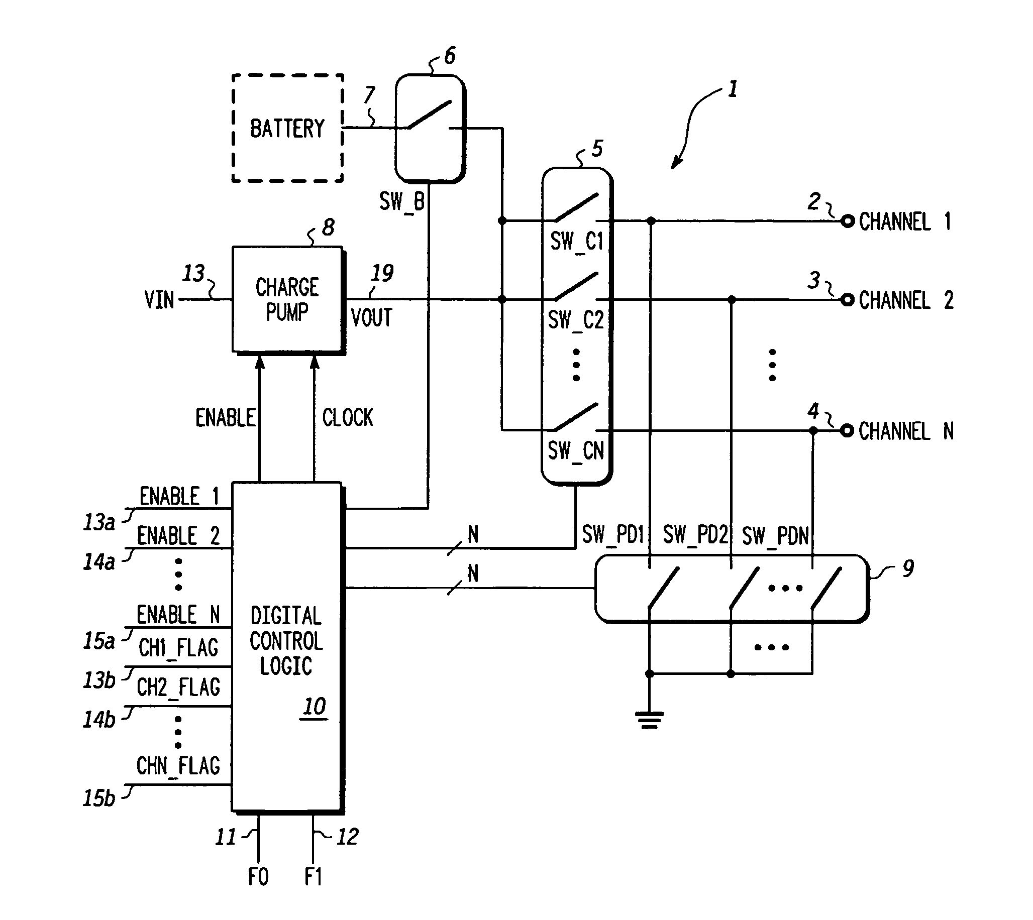
[0009]The power to an electronic circuit can be controlled by a switch disposed between a power supply and the electronic circuit. Multiple switches can be controlled using a charge pump to raise the voltage on a selected switch control input such that the switch closes and provides power to the circuit. One or more charge pumps can enable a larger total number of switches by selecting one or more channels to be charged or enabled by the charge pump. In order to decrease the time needed to enable the channels, the initial charging of the channel is done with a higher current capacity source, such as a battery, and the completion of the enablement is done with current supplied by the charge pump. The time duration use of the high capacity current source is set by a timer, and that of the charge pump is set by a timer or by measuring the voltage on the channels. The current needed by the voltage measurement circuit lowered by switching between a resistive voltage divider when the high...


PUM


Abstract

A switch controller has a charge pump, a selector switch connected to the charge pump, and a pre-charge power supply input connectable to the input of the selector switch. For each of the output channels being controlled, a power control switch is connected to an output of the selector switch. In response to commands, output channels are enabled and disabled, causing corresponding actions in the power control switches. When an output channel is to be activated, the output channel is selected by the selector switch and the pre-charge power supply connected to the input of the selector switch. The charging is completed by the charge pump and the enabled status of the power control switch is maintained by the charge pump.

Description

FIELD OF THE INVENTION[0001]This application relates to a charge pump and switch controller and a method of controlling the same.BACKGROUND OF THE INVENTION[0002]Electronic devices such as microprocessors in portable devices may be placed into states of operation which minimize the power requirements when some or all of the functions of the microprocessor are not being used. The voltage applied to the microprocessor or the portions of the circuitry thereof may be controlled such that either the entire microprocessor or a selected portion thereof is unpowered. In an unpowered state, power may be dissipated by leakage currents.[0003]Consistent with reducing the power consumption in the device for which the power is being controlled, power control apparatus may minimize power consumption through choice of components, the arrangement thereof, the sequence of operation, and other design factors. The number of components and the circuit physical area associated with the power control appa...

Claims


Application Information

Patent Timeline
Patent Type & Authority Patents(United States)
IPC IPC(8): H03K17/06
CPCH03K17/063
Inventor SCHLUETER, DAVID M.VOORWINDEN
Owner NXP USA INC
Why Eureka
Try Eureka