Spectroscopic device and raman spectroscopic system

a raman and spectroscopic technology, applied in the direction of spectrometry/spectrophotometry/monochromators, instruments, optical radiation measurement, etc., can solve the problem of regularly fixing fine particles, and achieve the effect of enhancing raman effect, simple design change, and enhancing raman

Active Publication Date: 2011-08-16
FUJIFILM CORP
View PDF12 Cites 7 Cited by
  • Summary
  • Abstract
  • Description
  • Claims
  • Application Information

AI Technical Summary

Benefits of technology

[0008]In view of the foregoing observations and description, the primary object of the present invention is to provide a Raman spectroscopic device in which the Raman effect enhancing wavelength can be more simply controlled as compared with the surface enhancing Raman device using local plasmon resonance and a Raman spectroscopic system using the Raman spectroscopic device.
[0020]Since the Raman spectroscopic device of the present invention comprises an optical resonator where the first reflecting body which exhibits semi-transmissivity / semi-reflectivity and has a surface which is a light scattering surface generating a Raman scattering, the transparent body and the second reflecting body which has a reflectivity are superposed in sequence one on another, and light traveling into the transparent body after transmitted by the first reflecting body repeats reflection between the first and second reflecting bodies to generate multiple reflection, whereby a multiple interference by the light reflected in the multiple reflection effectively takes place and the electric field of the optical resonator is enhanced at the resonant wavelength by the resonance generated by the multiple interference. Accordingly, the surface enhancing Raman effect is effectively obtained in the surface of the first reflecting body which is a light scattering surface.
[0021]Further, since in the Raman spectroscopic device of the present invention, the resonating wavelength changes according to the average refractive index and the thickness of the transparent body, and the Raman effect enhancing wavelength can be controlled by a simple design change where these factors are only changed. Accordingly, in accordance with the present invention, it is possible to obtain the Raman spectroscopic device having the surface enhancing Raman effect at a desired wavelength according to the application by a simple design change.

Problems solved by technology

Further, in Japanese Unexamined Patent Publication No. 2003-49205, there is not disclosed a method of regularly fixing the fine particles uniform in particle diameters to the metal body.

Method used


Image

  • Spectroscopic device and raman spectroscopic system
  • Spectroscopic device and raman spectroscopic system
  • Spectroscopic device and raman spectroscopic system

Examples


first embodiment

of the Raman Spectroscopic Device

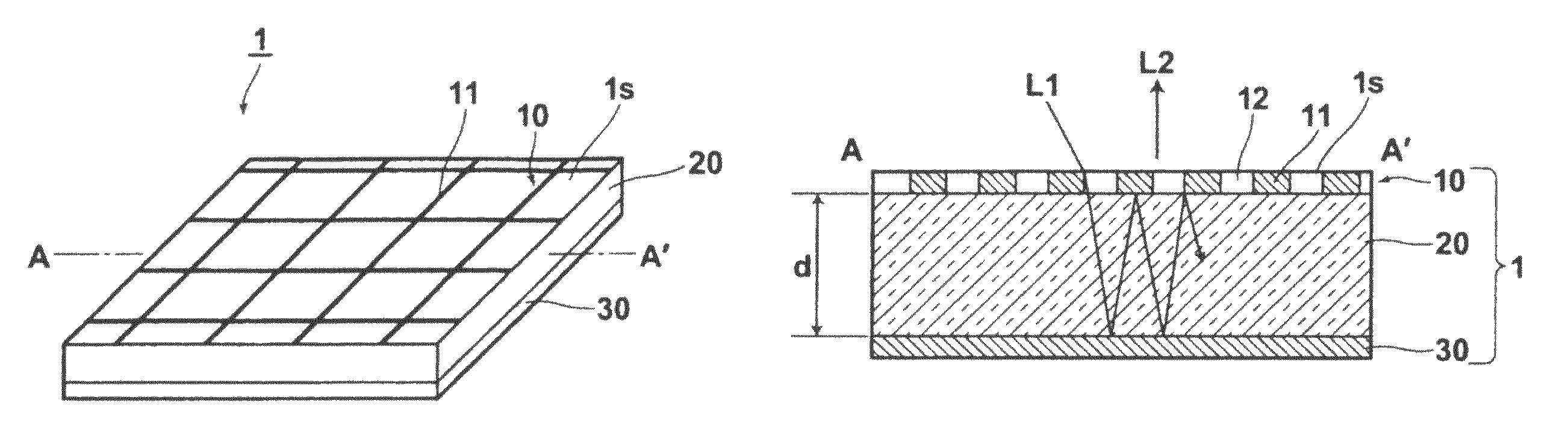
[0042]A Raman spectroscopic device in accordance with a first embodiment of the present invention will be described with reference to FIGS. 1A and 1B, hereinbelow. FIG. 1A is a perspective of the first embodiment and FIG. 1B is a cross-sectional view of the same (taken along line A-A′).

[0043]As shown in FIGS. 1A and 1B, the Raman spectroscopic device 1 in accordance with this embodiment comprises in sequence, from the incident side (from upward in FIGS. 1A and 1B) of measuring light L1, a first reflecting body 10 which exhibits semi-transmissivity / semi-reflectivity and has a surface which is a light scattering surface is generating a Raman scattering, a transparent body 20 and a second reflecting body 30 which has a reflectivity. The measuring light L1 is mono-wavelength light and the wavelength of the measuring light L1 is selected according to the material to be detected.

[0044]The transparent body 20 comprises a transparent flat substrate while the...

second embodiment

of the Raman Spectroscopic Device

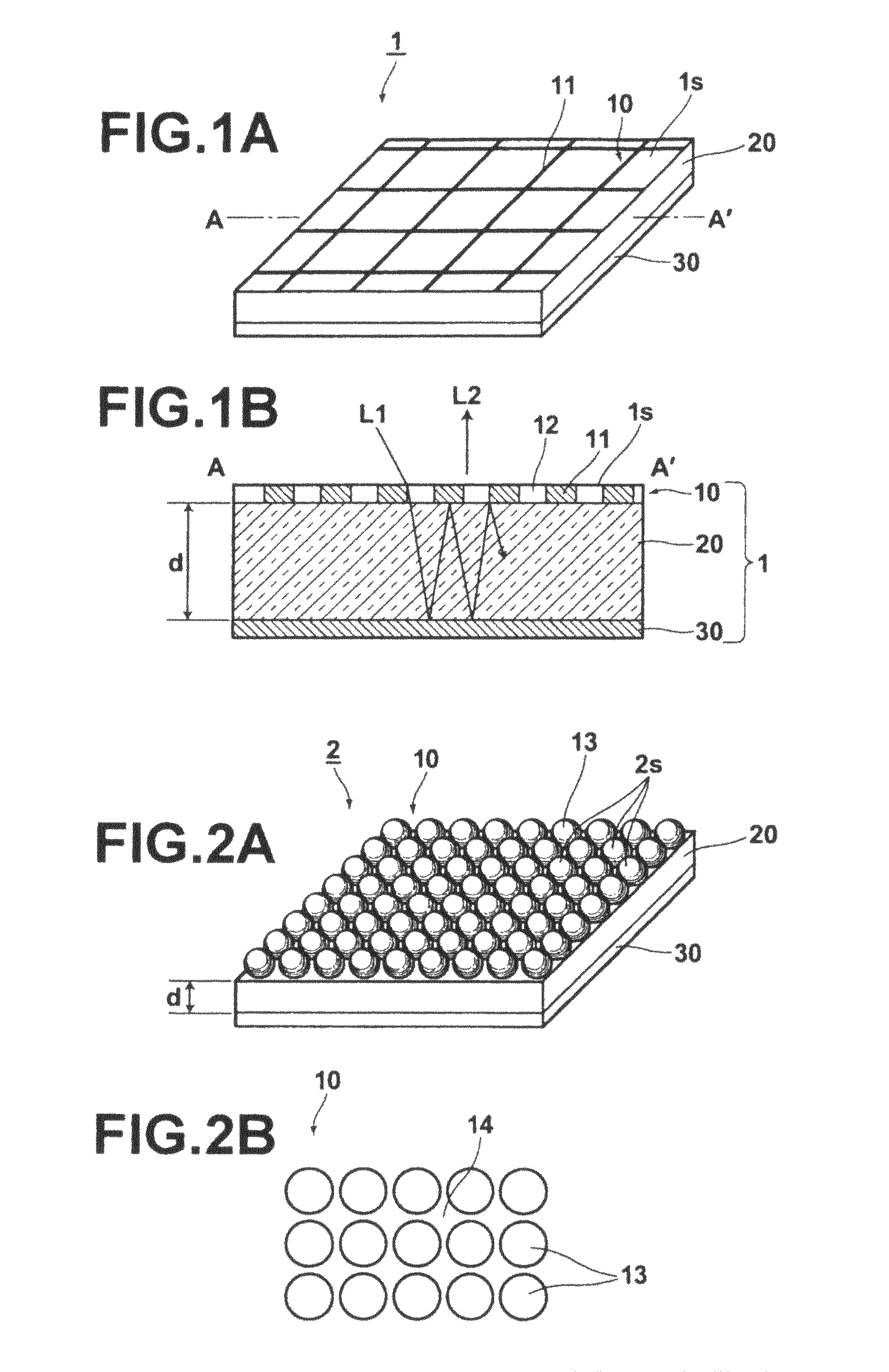
[0069]A Raman spectroscopic device of a second embodiment of the present invention will be described with reference to FIGS. 2A and 2B, hereinbelow. FIG. 2A is a perspective view similar to FIG. 1A of the first embodiment and FIG. 2B is a plan view of a Raman spectroscopic device. In this embodiment, the elements analogous to those in the first embodiment will be given the same reference numerals and will not be described.

[0070]As shown in FIGS. 2A and 2B, the Raman spectroscopic device 2 in accordance with this embodiment comprises similarly to the first embodiment, in sequence from the incident side of measuring light L1, a first reflecting body 10 which exhibits semi-transmissivity / semi-reflectivity and has a surface which is a light scattering surface 2s generating a Raman scattering, a transparent body 20 and a second reflecting body 30 which has a reflectivity.

[0071]The Raman spectroscopic device 2 in accordance with this embodiment differs fro...

third embodiment

of the Raman Spectroscopic Device

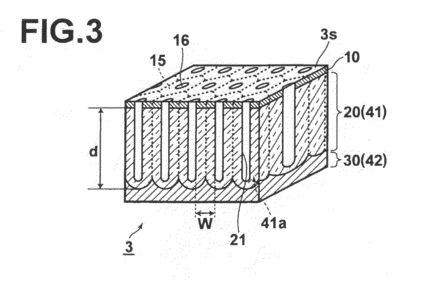
[0086]A Raman spectroscopic device of a third embodiment of the present invention will be described with reference to FIGS. 3 and 4A to 4C, hereinbelow. FIG. 3 is a perspective view of a Raman spectroscopic device and FIGS. 4A to 4C are views showing the manufacturing steps of the Raman spectroscopic device. In this embodiment, the elements analogous to those in the first embodiment will be given the same reference numerals and will not be described.

[0087]As shown in FIG. 3, the Raman spectroscopic device 3 in accordance with this embodiment comprises similarly to the first embodiment, in sequence from the incident side of measuring light L1, a first reflecting body 10 which exhibits semi-transmissivity / semi-reflectivity and has a surface which is a light scattering surface 3s generating a Raman scattering, a transparent body 20 and a second reflecting body 30 which has a reflectivity.

[0088]In this embodiment, different from the first embodiment, the...


PUM


Abstract

A Raman spectroscopic device includes an optical resonator, in which a first reflecting body that exhibits semi transmissivity / semi reflectivity and has a surface which is a light scattering surface that generates Raman scattering, a transparent body, and a second reflecting body that exhibits reflectivity, are laminated in sequence one on another. The Raman spectroscopic device utilizes light absorption due to resonance to obtain a surface amplified Raman effect.

Description

CROSS REFERENCE TO RELATED APPLICATION[0001]This application is a National Stage of International Application No. PCT / JP2007 / 061952 filed Jun. 7, 2007, claiming priority based on Japanese Patent Application Nos. 2006-159910 filed Jun. 8, 2006 and 2007-125270, filed May 10, 2007, the contents of all of which are incorporated herein by reference in their entirety.TECHNICAL FIELD[0002]This invention relates to a Raman spectroscopic device having a function of enhancing Raman scattering and a Raman spectroscopic system using the Raman spectroscopic device.BACKGROUND ART[0003]Raman spectroscopy is a method in which light of a mono-wavelength is projected onto a material and the obtained scattered light is spectroscopically (in a spectroscopic fashion) divided to obtain the Raman spectrum of Raman scattered light and is employed for, for instance, identification of the material. Since the Raman scattered light is weak, there has been developed surface enhancing Raman device where the Rama...

Claims


Application Information

Patent Timeline
Patent Type & Authority Patents(United States)
IPC IPC(8): G01J3/44
CPCG01N21/658G01N21/65B82B1/00G01N21/27B82Y35/00
Inventor NAYA, MASAYUKITANI, TAKEHARU
Owner FUJIFILM CORP
Why Eureka
Try Eureka