
Configuring a multi-processor system

Active Publication Date: 2011-08-16
XILINX INC
View PDF106 Cites 29 Cited by
  • Summary
  • Abstract
  • Description
  • Claims
  • Application Information

AI Technical Summary

Benefits of technology

In some embodiments, the channel is associated with a first port in the source processing element and a second port in the destination processing element. The channel may have a maximum number of buffers and a maximum size of the buffer. In some embodiments, the source processing node and the destination processing node reserve intermediate resources for the channel based on the bandwidth requirements. In some embodiments, the source processing node guarantees bandwidth based on the bandwidth requirements using time division multiplexing. In some embodiments, the source processing node guarantees bandwidth based on the bandwidth requirements using spatial division multiplexing. The source processing element may free the transmit buffer, and the destination processing element may free the receive buffer.

Problems solved by technology

Computationally intensive applications, such as modeling nuclear weaponry, simulating pharmaceutical drug interactions, predicting weather patterns, and other scientific applications, require a large amount of processing power.
These conventional approaches, however, cannot make many assumptions about (i.e., predict) or adapt their resources to optimize computations and communications in accordance with the user's application.
This deficiency exists because the number of applications varies widely and each often has requirements that vary dynamically over time, depending on the amount of resources required.
Also, those approaches that are focused on one particular application often provide high performance for only one specific application and thereby are inflexible to a user's changing needs.
Further, the traditional approaches do not allow a user to optimize the amount of hardware for the user's specific application, resulting in a multiprocessor architecture with superfluous resources, among other deleterious effects.
Additionally, conventional approaches do not optimize communications among processors of a multiprocessor architecture for increased speeds and / or do not easily allow scalability of the processors of such an architecture.
However, cache coherency is expensive in terms of hardware, for example, and does not scale well as the number of nodes increases.
Scaling cache coherency beyond four nodes usually requires significant hardware complexity.
Furthermore, message passing machines and architectures often have additional hardware overhead as each processor element must have its own copy of the program for execution.
These interface protocols have been primarily used in high-performance processing systems such as super computers, which are very expensive.
These general purpose processing systems are more expensive than embedded systems because the general purpose processing systems have to include additional functionality to run a variety of applications that may change dynamically.
However, one problem with MPI is that the communications between the source and destination are not guaranteed.
Thus, some packets of data sent under MPI can get lost.
Another problem with MPI is that there is no mechanism for a reservation of bandwidth.
One problem with this queuing is the delay experienced by having many connections, which decreases overall application performance.
However, one problem with sockets is that in order to provide this reliability, large amounts of buffering are required.
Another problem is that the operation of sockets is expensive in terms of performance and processing cycles.
Standard C and C++ compilers do not provide the required functionality for a multi-processor environment.
However, one problem is that VX Works only has limited functionality for a multi-processor system.
Specifically, the linker, debugger, and system description framework do not support multi-processor systems.
One problem is that not all multi-processor systems have FLASH memory associated with the processor.

Method used


Image

  • Configuring a multi-processor system
  • Configuring a multi-processor system
  • Configuring a multi-processor system

Examples


Embodiment Construction

As shown in the exemplary drawings wherein like reference numerals indicate like or corresponding elements among the figures, exemplary embodiments of a system and method according to the present invention are described below in detail. It is to be understood, however, that the present invention may be embodied in various forms. Therefore, specific details disclosed herein are not to be interpreted as limiting, but rather as a basis for the claims and as a representative basis for teaching one skilled in the art to employ the present invention in virtually any appropriately detailed system, structure, method, process or manner.

Processing System—FIGS. 1-2

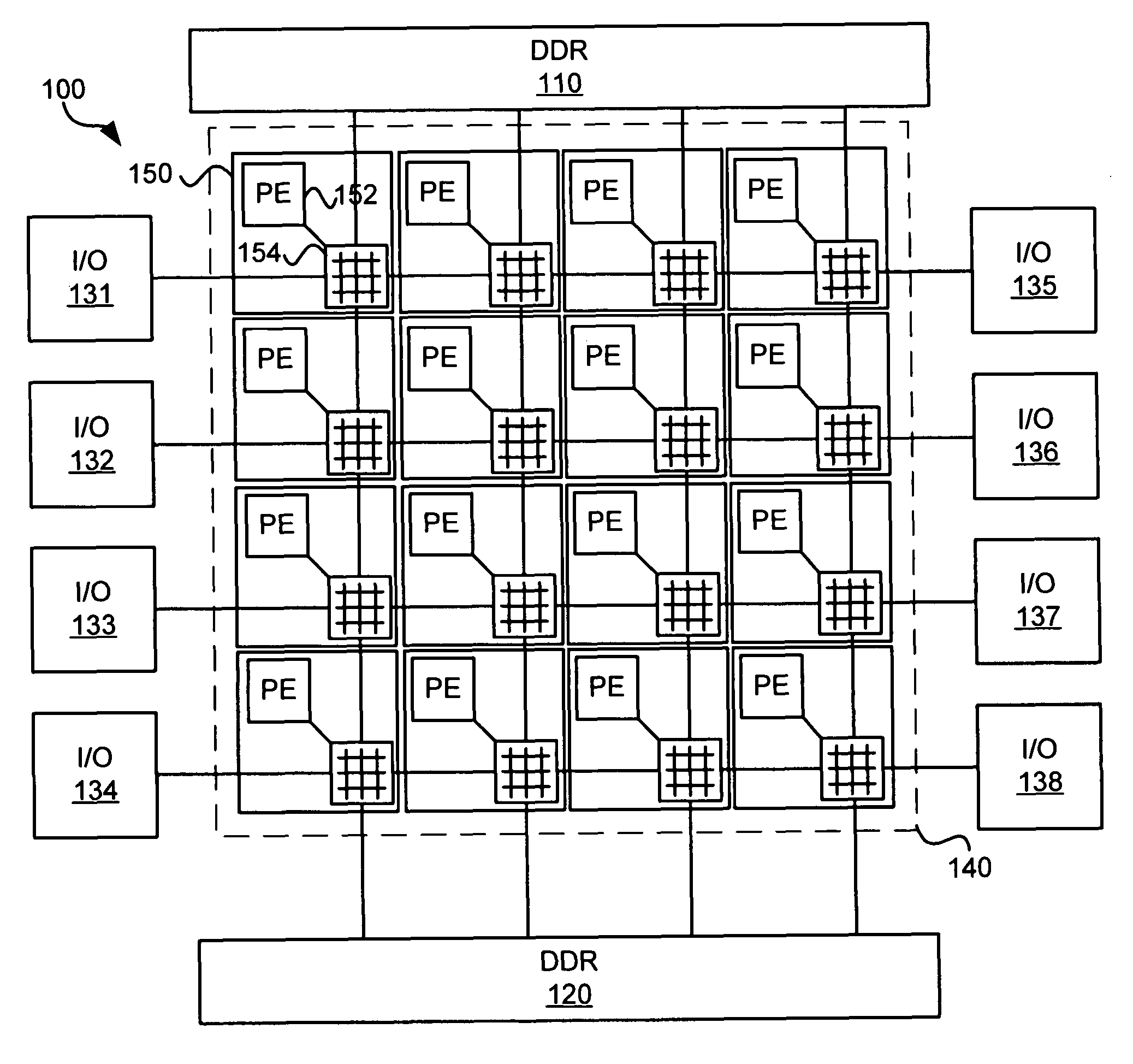
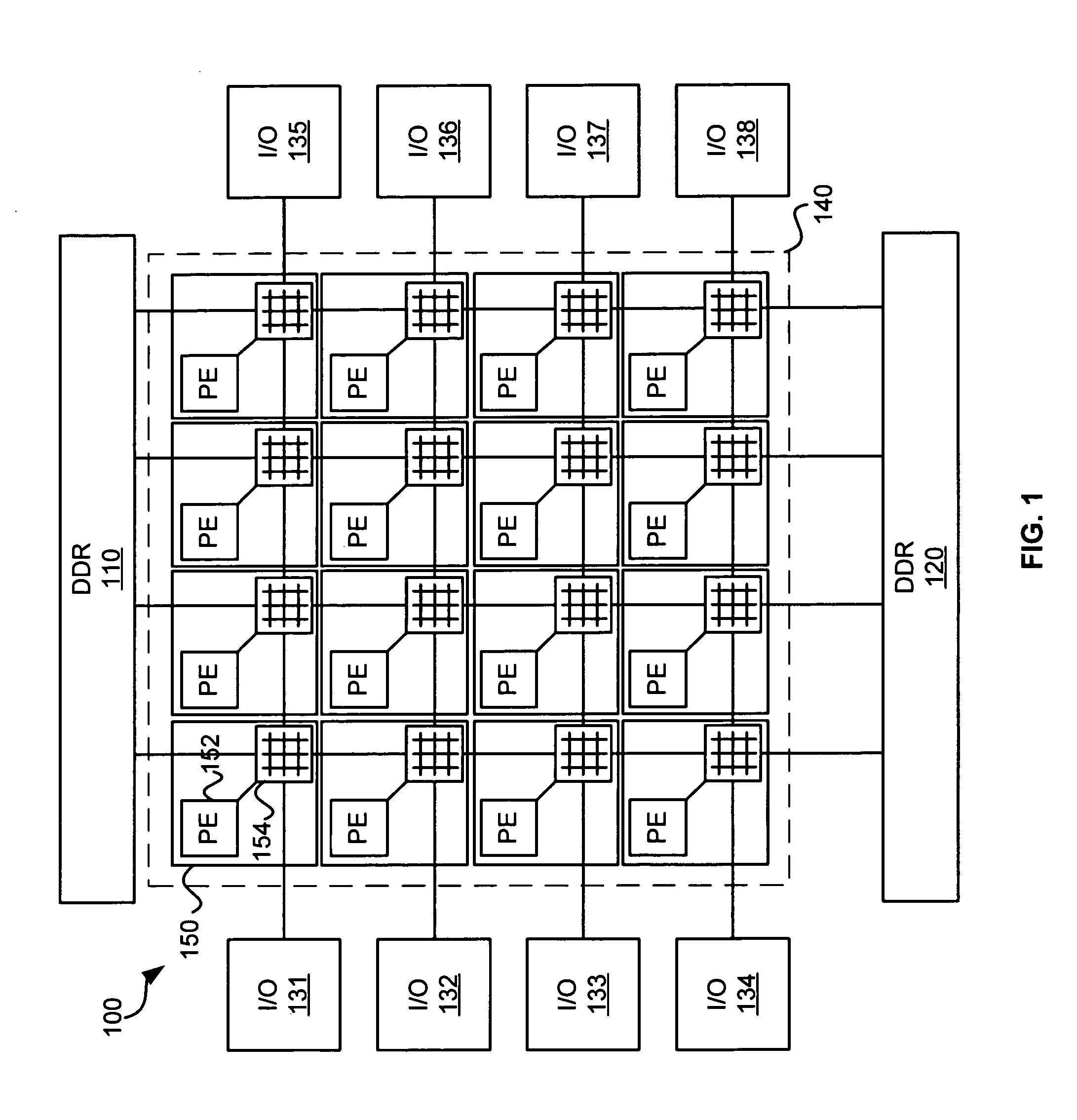
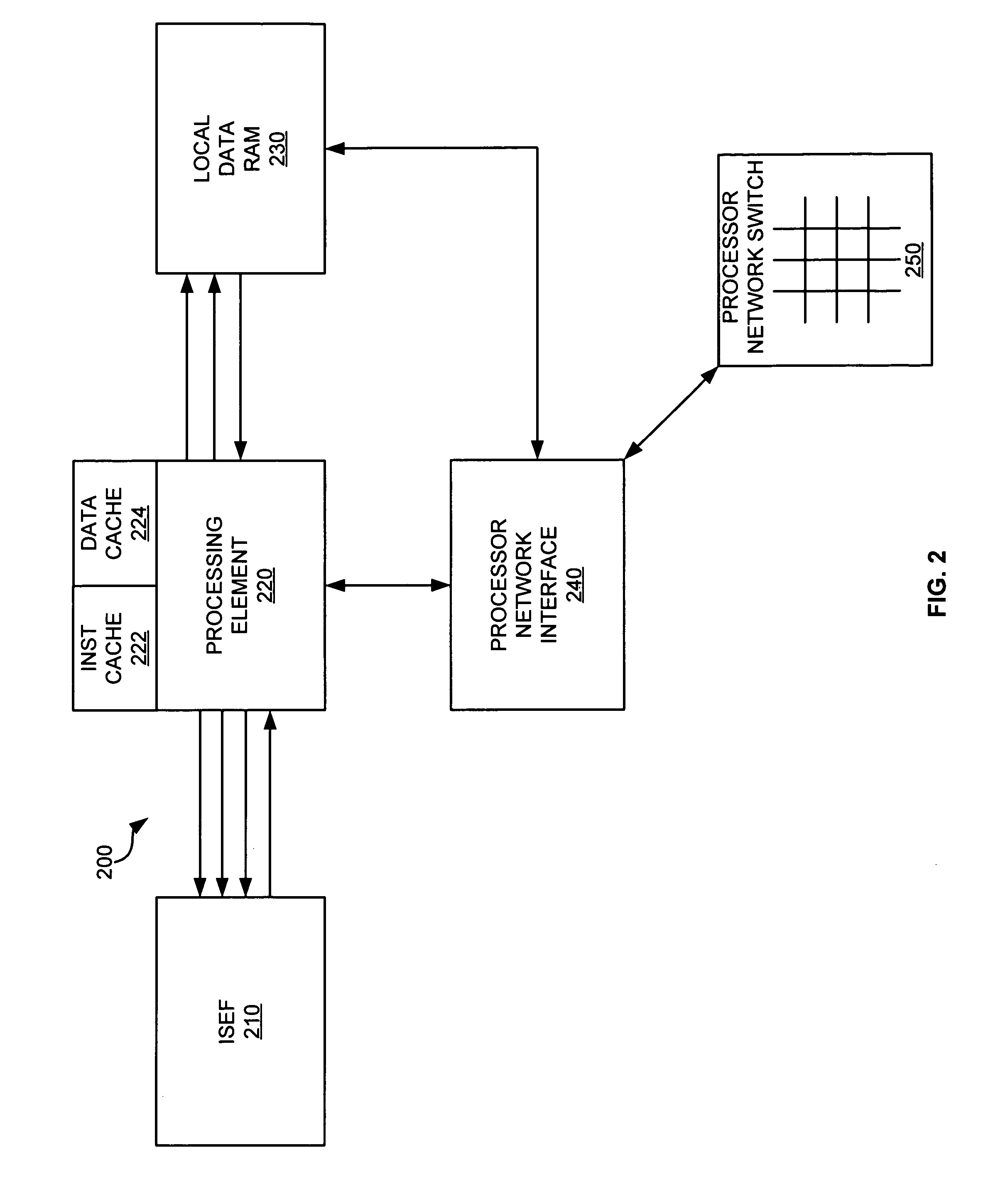
FIG. 1 depicts a diagram of a processing system 100 in an exemplary implementation of the invention. The processing system 100 includes Double Data Rate (DDR) memory controllers 110 and 120, Input / Output (I / O) devices 131-138, and an array of processor nodes 140. In this embodiment, the array of processor nodes 140 is a four by four ...


PUM


Abstract

A source processing node communicates with a destination processing node though a channel that has bandwidth requirements and is uni-directional. The source processing node generates the channel to the destination processing node. The destination processing node then accepts the channel. The source processing node allocates a transmit buffer for the channel. The destination processing node also allocates a receive buffer for the channel. A source processing element writes data to the transmit buffer for the channel. A source network interface transmits the data from the transmit buffer of the source processing node over the channel. A destination network interface receives the data into the receive buffer for the channel. A destination processing element receives the data from the receive buffer.

Description

BACKGROUND1. Field of the InventionThe present invention relates generally to processing systems, and more particularly to configuring a multi-processor system.2. Description of the Prior ArtComputationally intensive applications, such as modeling nuclear weaponry, simulating pharmaceutical drug interactions, predicting weather patterns, and other scientific applications, require a large amount of processing power. General computing platforms or engines have been implemented to provide the computational power to perform those applications. Such general computer computing platforms typically include multiple single-chip processors (i.e., central processor units, or CPUs) arranged in a variety of different configurations. The number of CPU's and the interconnection topology typically define those general computing platforms.To improve the functionality, reduce cost, increase speed, etc. of the general computer computing platforms, the multiprocessors and their architectures are migrat...

Claims


Application Information

Patent Timeline
IPC IPC(8): G06F15/173
CPCG06F15/177G06F9/544
Inventor GONZALEZ, RICARDO E.RUDELL, RICHARD L.GHOSH, ABHIJITWANG, ALBERT R.
Owner XILINX INC
Learn More