
Wear leveling for low-wear areas of low-latency random read memory

a random read and low-latency technology, applied in the field of storage systems, can solve the problems of increasing the current rate of wear of the erase-unit, and achieve the effects of increasing the current rate of wear, low wear count, and high wear coun

Active Publication Date: 2011-08-16
NETWORK APPLIANCE INC
View PDF5 Cites 91 Cited by
  • Summary
  • Abstract
  • Description
  • Claims
  • Application Information

AI Technical Summary

Benefits of technology

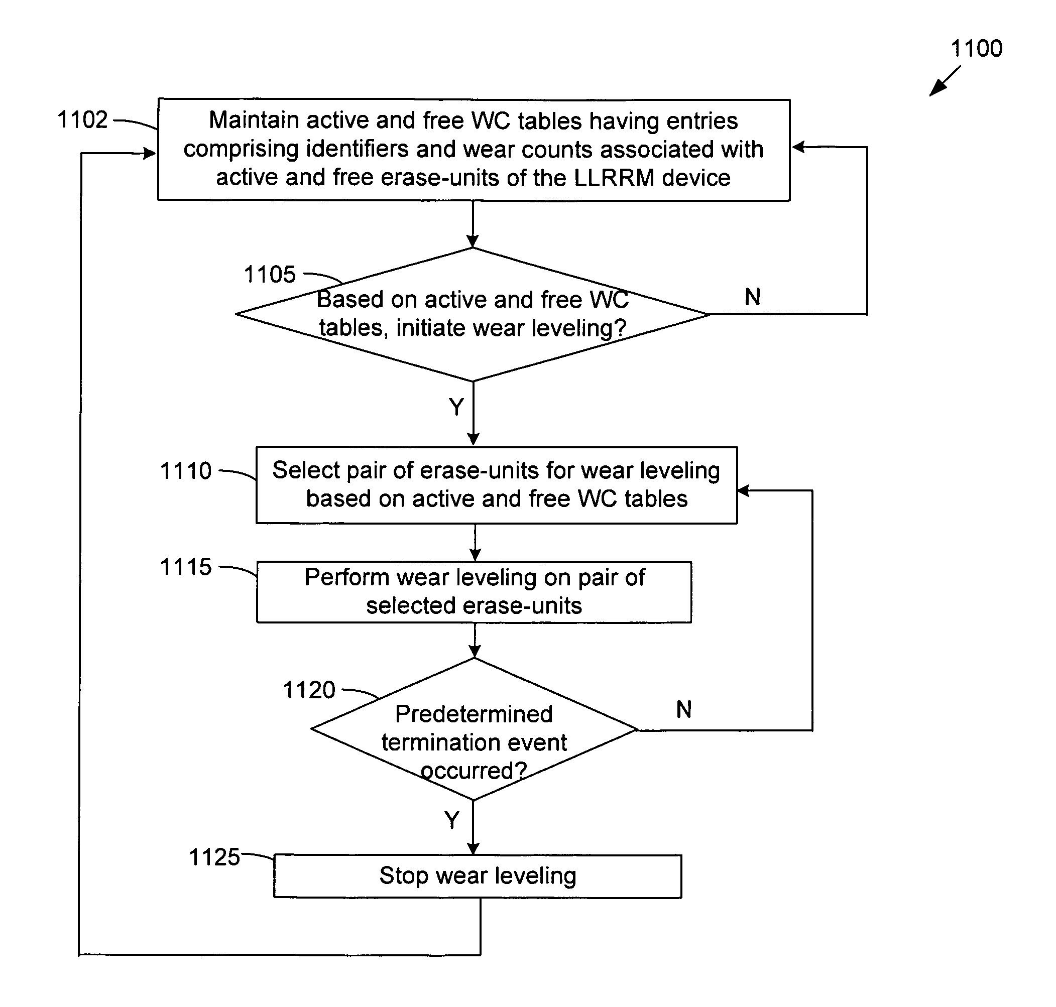
[0008]Described herein are method and apparatus for providing wear leveling of erase-units of the LLRRM device that considers all active erase-units (having client data). In some embodiments, all erase units of an LLRRM device are considered to determine active erase-units that have been erased / written relatively infrequently (referred to as “low-wear” active erase-units having relatively low wear counts) and free erase-units (not having client data) that have been erased / written relatively frequently (referred to as “high-wear” free erase-units having relatively high wear counts). An active erase-unit may have a low wear count because the client data stored in the active erase-unit has not been overwritten in some time (i.e., is “cold”). In some embodiments, the client data of low-wear active erase-units are transferred to high-wear free erase-units. Thus a low-wear active erase-unit may be converted to a free erase-unit, which puts the active erase-unit back into circulation for use in the LLRRM device, whereby it may later store different client data that is frequently overwritten (i.e., is “hot”). As such, the current rate of wear for the erase-unit may be increased. Further, a high-wear free erase-unit may be converted to an active erase-unit that stores client data that is infrequently erased / written, which may thereby reduce the current rate of wear for the erase-unit. As such, some embodiments herein spread wear more evenly among erase-units by reducing the current wear rate of low-wear active erase-units and increasing the current wear rate of high-wear free erase-units.
[0016]Due to the maximum wear characteristics of erase-units of an LLRRM device, wear leveling may used to help distribute wear (i.e., the number of erase cycles) evenly among the erase-units to preserve the full storage size of the LLRRM device. In some embodiments, a wear leveling method is provided that converts low-wear active erase-units (having relatively low wear counts) to free erase-units that may later store different client data, which may thereby increase the current rates of wear for these erase-units. Further, high-wear free erase-units (having relatively high wear counts) may be converted to active erase-units that store client data that are infrequently erased / written, which may thereby reduce the current rates of wear for these erase-units. As such, some embodiments herein spread wear more evenly among erase-units by reducing the current wear rates of low-wear active erase-units and increasing the current wear rates of high-wear free erase-units.

Problems solved by technology

As such, the current rate of wear for the erase-unit may be increased.

Method used


Image

  • Wear leveling for low-wear areas of low-latency random read memory
  • Wear leveling for low-wear areas of low-latency random read memory
  • Wear leveling for low-wear areas of low-latency random read memory

Examples


Embodiment Construction

[0028]In the following description, numerous details are set forth for purpose of explanation. However, one of ordinary skill in the art will realize that the embodiments described herein may be practiced without the use of these specific details. In other instances, well-known structures and devices are shown in block diagram form in order not to obscure the description with unnecessary detail.

[0029]The description that follows is divided into three sections. Section I describes a storage system environment in which some embodiments operate. Section II describes a storage operating system having a remapping layer for using LLRRM as a storage device in a storage system. Section III describes performing wear leveling on selected erase-units of an LLRRM device.

I. Storage System Environment

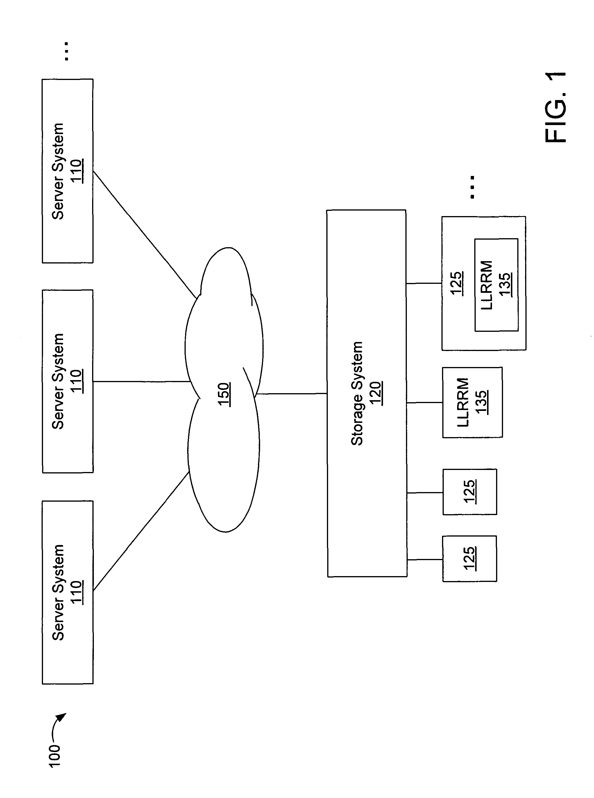
[0030]FIG. 1 is a schematic block diagram of an exemplary storage system environment 100 in which some embodiments operate. The environment 100 comprises a one or more server systems 110 and a storag...


PUM


Abstract

Described herein are method and apparatus for performing wear leveling of erase-units of an LLRRM device that considers all active erase-units. Wear counts of all active erase-units (containing client data) and free erase-units (not containing client data) are tracked. Wear counts are used to determine low-wear active erase-units having relatively low wear counts and high-wear free erase-units having relatively high wear counts. In some embodiments, data contents of low-wear active erase-units are transferred to high-wear free erase-units, whereby the low-wear active erase-units are converted to free erase-units and may later store different client data which may increase the current rate of wear for the erase-unit. The high-wear free erase-units are converted to active erase-units that store client data that is infrequently erased / written, which may reduce the current rate of wear for the erase-unit. As such, wear is spread more evenly among erase-units of the LLRRM device.

Description

FIELD OF THE INVENTION[0001]The present invention relates to storage systems, and particularly, to wear leveling for low-wear areas of low-latency random read memory.BACKGROUND OF THE INVENTION[0002]A storage system is a processing system adapted to store and retrieve data on storage devices (such as disks). The storage system includes a storage operating system that implements a file system to logically organize the data as a hierarchical structure of directories and files on the storage devices. Each file may be implemented as a set of blocks configured to store data (such as text), whereas each directory may be implemented as a specially-formatted file in which data about other files and directories are stored. The storage operating system may assign / associate a unique storage system address (e.g., logical block number (LBN)) for each data block stored in the storage system.[0003]The storage operating system generally refers to the computer-executable code operable on a storage s...

Claims


Application Information

Patent Timeline
IPC IPC(8): G06F12/16G06F11/22
CPCG06F12/0246G06F2212/7211
Inventor IYER, RAHUL N.GOODSON, GARTH R.
Owner NETWORK APPLIANCE INC
Learn More