Filter bag and method for the production thereof

a technology of filter bags and vacuum cleaners, applied in the direction of suction filters, colloidal chemistry details, paper/cardboard containers, etc., can solve the problems high cost of the method described in de 100 64 608 a1, and achieve the effect of low flexural strength, easy fitting into a vacuum cleaner, and increased stability of the bottom formed

Active Publication Date: 2011-08-23
EUROLIFTERS HLDG NV
View PDF32 Cites 18 Cited by
  • Summary
  • Abstract
  • Description
  • Claims
  • Application Information

AI Technical Summary

Benefits of technology

[0011]The crucial advantage of the solution according to the invention can be seen in the fact that, due to the central weld seam and the at least partial connection of the plies folded over one another, stabilisation of the bottom is achieved which is sufficient to make available, even from a material which is low in flexural strength, a vacuum cleaner bag which can be provided at any point with a retaining plate and which can therefore be easily fitted into a vacuum cleaner. What should be further stressed about the solution according to the invention is that the design of the retaining plate can be freely selected. With the solution according to the invention it is thus possible to attach retaining plates which not only have an opening but which are additionally provided with slides or flaps for sealing the opening. According to the present invention, it is also possible not to attach the retaining plate directly on the bottom but it can also be arranged on the longitudinal surfaces of the vacuum cleaner bag.
[0012]With the vacuum cleaner bag according to the invention it is preferred for the central weld seam to extend over the entire width of the bottom. In this way an increased stability of the bottom formed by the folding is achieved. Connecting the superposed plies which have been formed by the fold takes place preferably by welding or gluing. This gluing or welding can take place in a linear manner. Thus a directed reinforcement of the bottom can be achieved.
[0013]In the case of the vacuum cleaner bag according to the invention it is furthermore propitious if pre-creases are introduced over the longitudinal sides, i.e. over those surfaces of the vacuum cleaner bag which lie between the closed free end and the at least partially closed end having the bottom designed according to the invention, into the thus spread-apart side surfaces so that folding is possible. The pre-creases can be so designed that they start e.g. from the respective corners of the bottom, if it is angular, e.g. square, and are led to the opposite free end. It is advantageous moreover if, in addition, starting from the central weld seam, a further pre-crease is introduced into the bag material in each case. Thus the introduction of side folds is facilitated and the surface of the vacuum cleaner bag is enlarged. Simultaneously, the pre-creases introduced into the longitudinal sides of the vacuum cleaner bag can serve to further stabilise the bag material. Under “pre-creases” in the sense of the invention are understood material compressions which are preferably configured linear. The pre-creases can be introduced by a suitable forming tool and / or by welding.
[0017]It is advantageous furthermore that, due to the stabilisation of the bottom as such, one-piece retaining plates can be used. These can also then be provided with a closing mechanism.
[0019]According to the present invention, however, it is also possible for the retaining plate to be arranged on the side surfaces of the vacuum cleaner bag. It is preferred here for the retaining plate to be attached in the vicinity of the bottom of the bag since thus the bag interior freely spread-apart by the bottom can be used for introducing a filling nozzle and for advantageous air conduction.

Problems solved by technology

As a result of this bag material being low in flexural strength however, the formation of a square bottom is only possible with difficulty or with great outlay.
The method described in DE 100 64 608 A1 is very expensive however.
What is disadvantageous about this solution is that no bottom is formed here which stabilises the bag per se, but that a reinforcing means, i.e. a retaining plate, must always inevitably be attached.
Thus this bag is subject to great restrictions in relation to its application in the field of vacuum cleaners, since the retaining plate regularly has to fulfill a plurality of functions.
This is not possible with a foldable embodiment of the retaining plate.
It is also not possible to attach the retaining plate e.g. on the longitudinal sides of the bag since there is no bottom present to stabilise the bag.

Method used


Image

  • Filter bag and method for the production thereof
  • Filter bag and method for the production thereof
  • Filter bag and method for the production thereof

Examples


Embodiment Construction

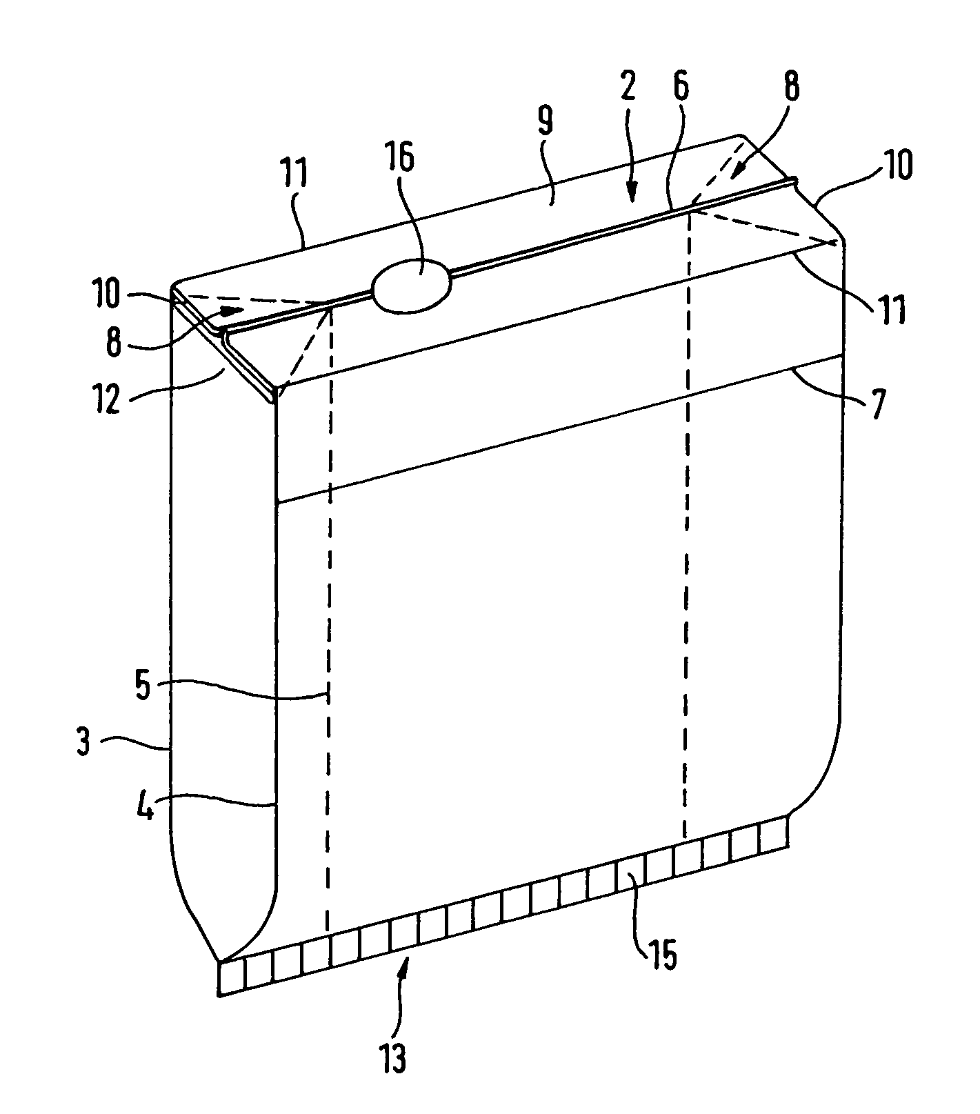
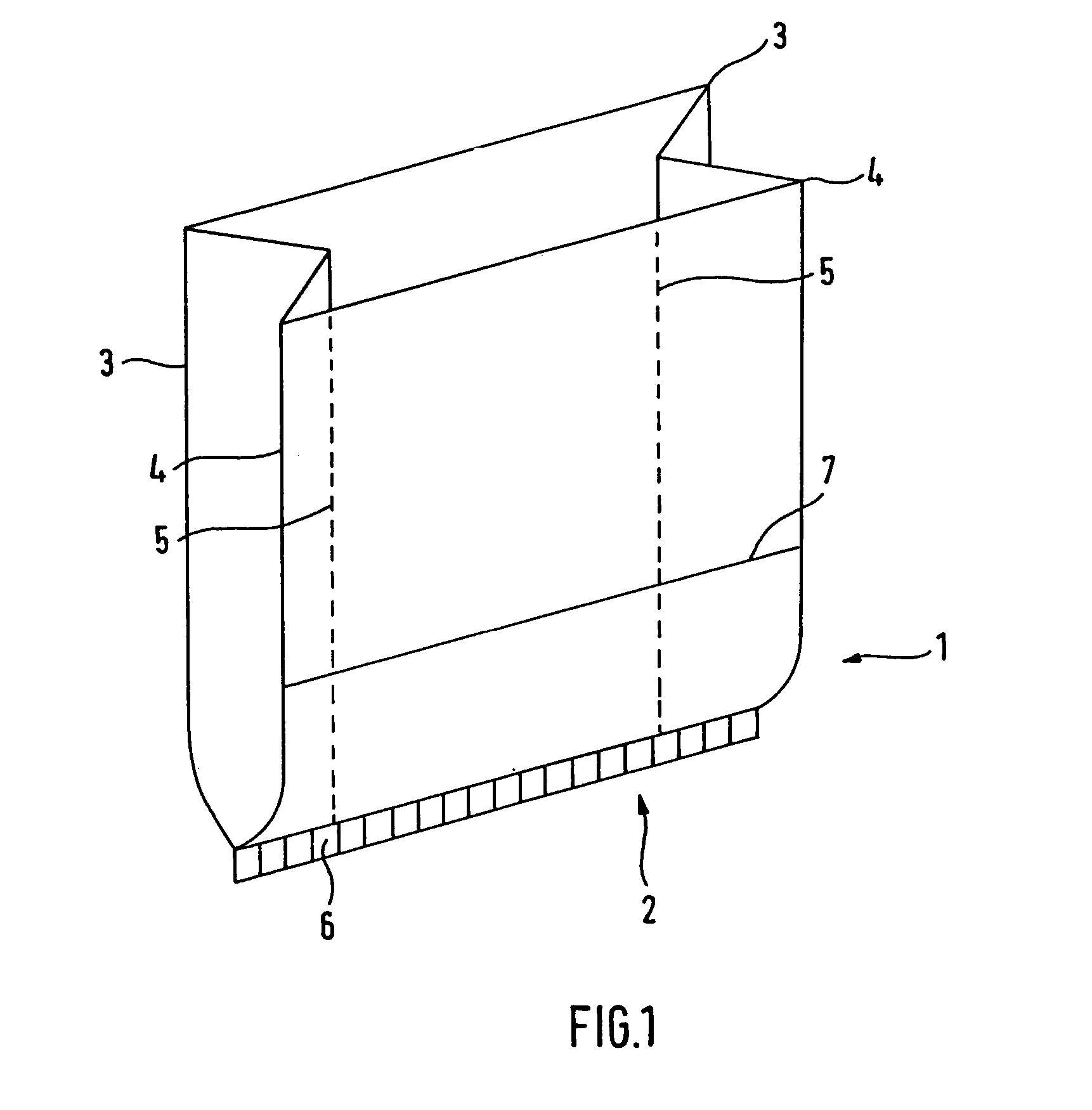
[0038]FIG. 1 shows an exemplary embodiment of the filter bag 1 according to the present invention schematically in the state resulting from the formation of the tubular bag and the closing of the free end area (method step a)). The filter bag 1 here consists of a composite non-woven material, such as is described in WO 01 / 03802 A1. In the embodiment according to FIG. 1, the filter bag has pre-creases 3, 4 and 5 which lead to the illustrated fold formation. As “pre-crease” is here understood a material compression. This can be produced either by pressure or by pressure and temperature. Due to the pre-creases 3, 4 and 5, a folded tubular filter bag is produced which is sealed at its closed end 2 by a weld seam 6.

[0039]In the embodiment according to FIG. 1, the central weld seam 6 is introduced by thermowelding. The welding is here so executed that the two superposed plies of the filter material have been interconnected by the welding. The filter bag according to FIG. 1 has in addition...


PUM

PropertyMeasurementUnit
areaaaaaaaaaaa
widthaaaaaaaaaa
shapeaaaaaaaaaa

Abstract

Described is a filter bag for a vacuum cleaner which may include a tubular bag with a closed free end area and an opposed, at least partially closed area as well as with a retaining plate. The bag is made from a bag material having at least one non-woven layer, and the at least partially closed area is folded forming a bottomPlies of the bag material which lie the one above the other are formed in areas, and is at least partially closed by a weld seam extending centrally in the bottom, the plies of the bag material which lie the one above the other being at least partially connected to one another.

Description

FIELD OF INVENTION[0001]The present invention relates to a filter bag for a vacuum cleaner which has a tubular bag and a closed free end area and an opposed, at least partially closed area, as well as a retaining plate, the partially closed area being folded forming a bottom.BACKGROUND INFORMATION[0002]Filter bags for vacuum cleaners which have a tubular bag and, as well as a closed free end area, a folded bottom, a so-called “square bottom”, are known in the prior art. Usually such dust bags are produced from a paper material which can be processed on standard tubular bag systems. In the case of such filter bags, an appropriate retaining plate is generally attached to the square bottom and has an opening through which the air to be cleaned is led. The task of the square bottom is to stabilise the filter bag and form a three-dimensional bag. Moreover the square bottom makes it easier to fit the bag into the vacuum cleaner.[0003]Recently however, new developments have become known in...

Claims


Application Information

Patent Timeline
Patent Type & Authority Patents(United States)
IPC IPC(8): B01D46/02A47L9/14B31B29/00B31B41/00
CPCA47L9/14B31B29/00B31B41/00B31B2221/20Y10S55/02B31B2241/008Y10T156/1069Y10T156/1739Y10T156/1079B31B2221/407B31B2150/00B31B2160/20B31B2150/0016B31B2150/001
Inventor SCHULTINK, JAN
Owner EUROLIFTERS HLDG NV
Why Eureka
Try Eureka