

Linear explosive breaching apparatus and method
a linear explosive and target technology, applied in the direction of explosive charges, metal working apparatuses, weapons, etc., can solve the problems of complex effective range of tampering mass when associated with high explosive charges, leaking charges, and creating a slippery environment for operators
- Summary
- Abstract
- Description
- Claims
- Application Information
AI Technical Summary
Benefits of technology
Problems solved by technology
Method used
Image

Examples
example 1
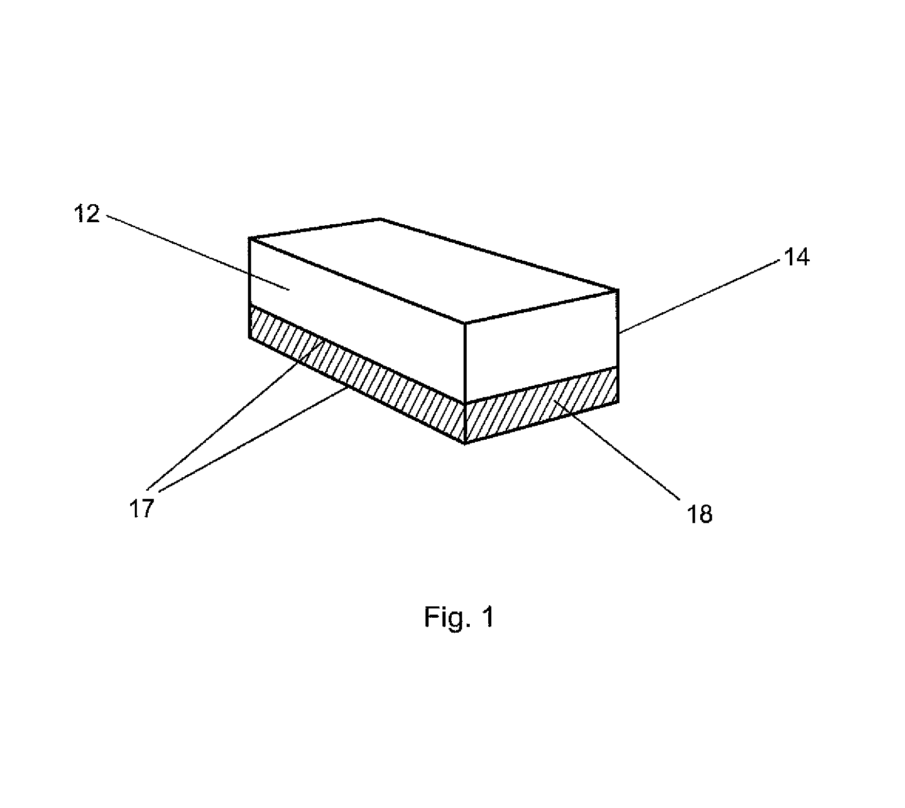
[0128]One embodiment of the present invention comprises inert material as a rectangular shaped slab or a hemicylindrical shaped piece of plastic material such as high density polyethylene with a rectangular slab of sheet explosive on top. For the angled type geometries (see drawings) the range of effective angles would be from 30-120 degree and the geometric shape could also be parabola or hemicylindrical or hemispherical in shape. The optimum angle range is from 90-120 degrees with a hemicylindrical (for linear geometries) being also very efficient.
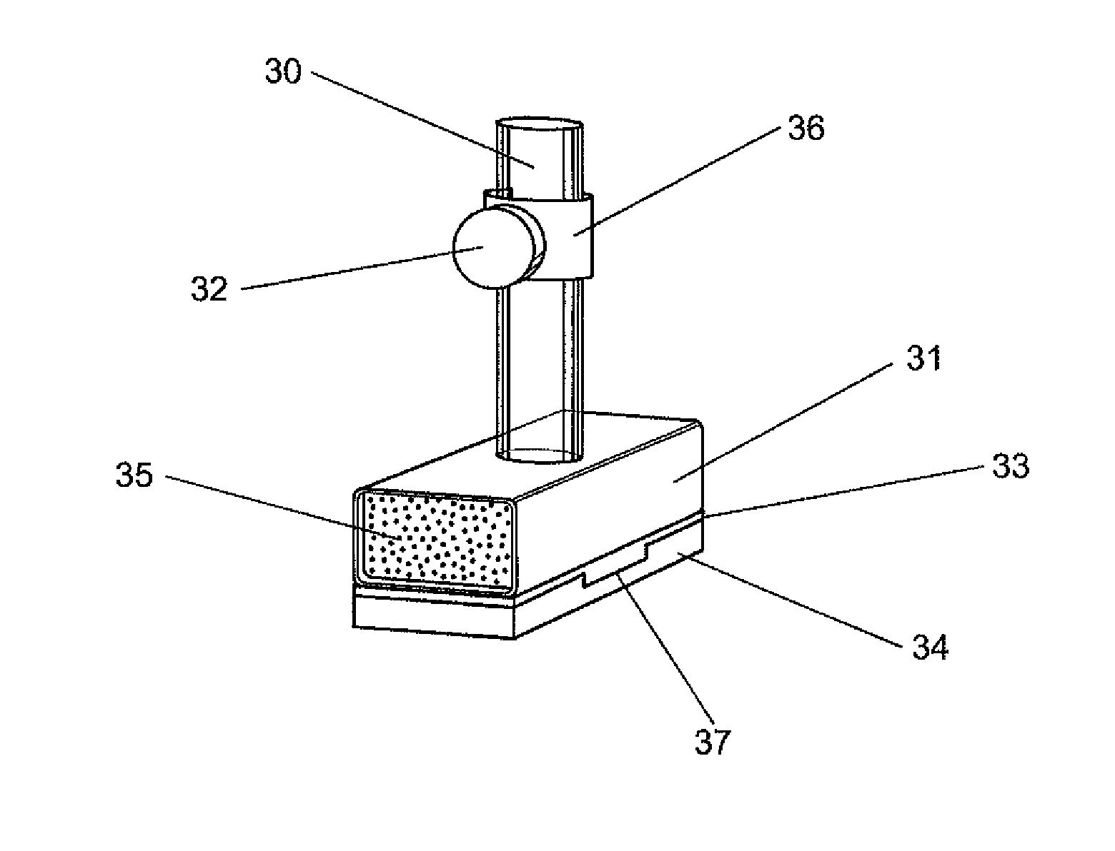
[0129]In one embodiment of the present invention, a miniature explosive breaching apparatus using a shock lensing material and frangible tamper mass successfully breached a deadbolt mechanism on a 1.75″ thick exterior wooden door. The charge consisted of a right prism shaped shock lensing material enveloped by 2.4 grams of 2 mm thick sheet explosive and a frangible tamper mass consisting of spheroidal tungsten powder. The spheroidal tung...
example 2
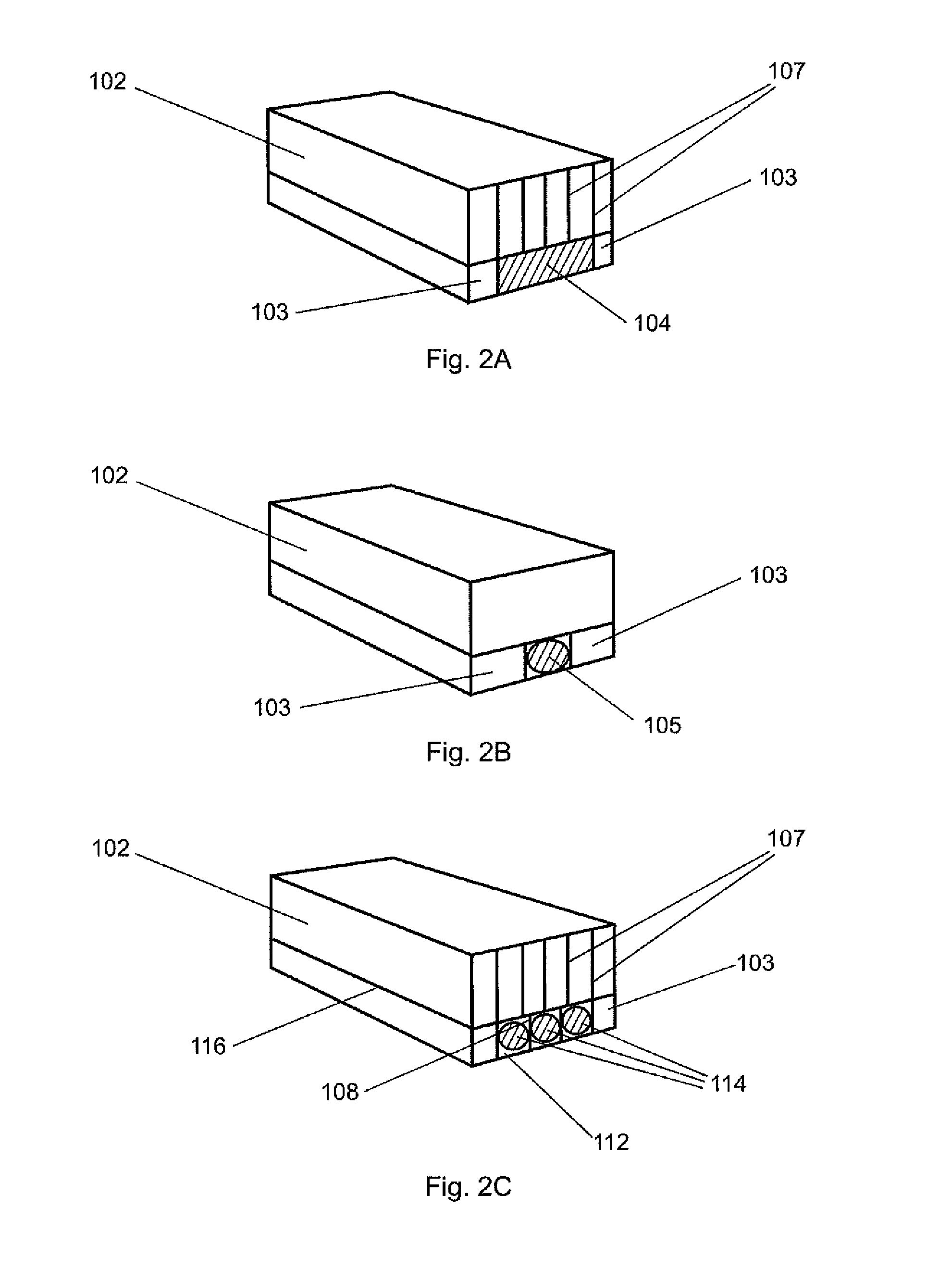
[0132]The present invention, a 8″ long×0.75″ wide explosive breaching apparatus using a shock spreading material and a frangible tamper mass successfully breached a deadbolt and a door lock mechanism on a 1.75″ thick exterior wooden door. The charge consisted of 6.6 grams of a 1 mm thick piece of sheet explosive sandwiched between a 0.25″ thick polyethylene shock spreading material and a frangible tamper mass consisting of spheroidal steel powder housed in a thin soft plastic container. The spheroidal steel powder ranged from 125 to 180 microns in diameter. Detonators were placed in the detonator wells and secured with fasteners to ensure intimate contact with the sheet explosive. Three panels of 0.25″ thick soft foam poster board were placed directly behind the charge at a 7′ standoff in order to determine potential hazards from the frangible tamper masses. After removal of the adhesively connected insulation, the charge was positioned and secured between the deadbolt and door lock...
example 3
[0135]In one embodiment of the present invention, two miniature explosive breaching charge apparatuses using shock spreading materials and frangible tamper mass successfully breached a deadbolt and a door lock mechanism on a 1.75″ thick exterior wooden door. The charges each consisted of 3.75 grams of 2 mm thick piece of sheet explosive 33 sandwiched between a 0.1875″ thick polyethylene shock spreading material and a frangible tamper mass comprising of spheroidal tungsten powder. The spheroidal tungsten powder tamper particles ranged from 40 to 50 microns in diameter. Shock tube detonators were disposed within the detonator wells, seated through the frangible tamping material. The detonators were secured within the detonator wells with a fastener within the tube and placed in intimate contact with the sheet explosives contained within the charge. The shock tube detonators were linked together using a shock tube tee for simultaneous initiation. After removal of the adhesively connect...
PUM
 Abstract
Description
Claims
Application Information