

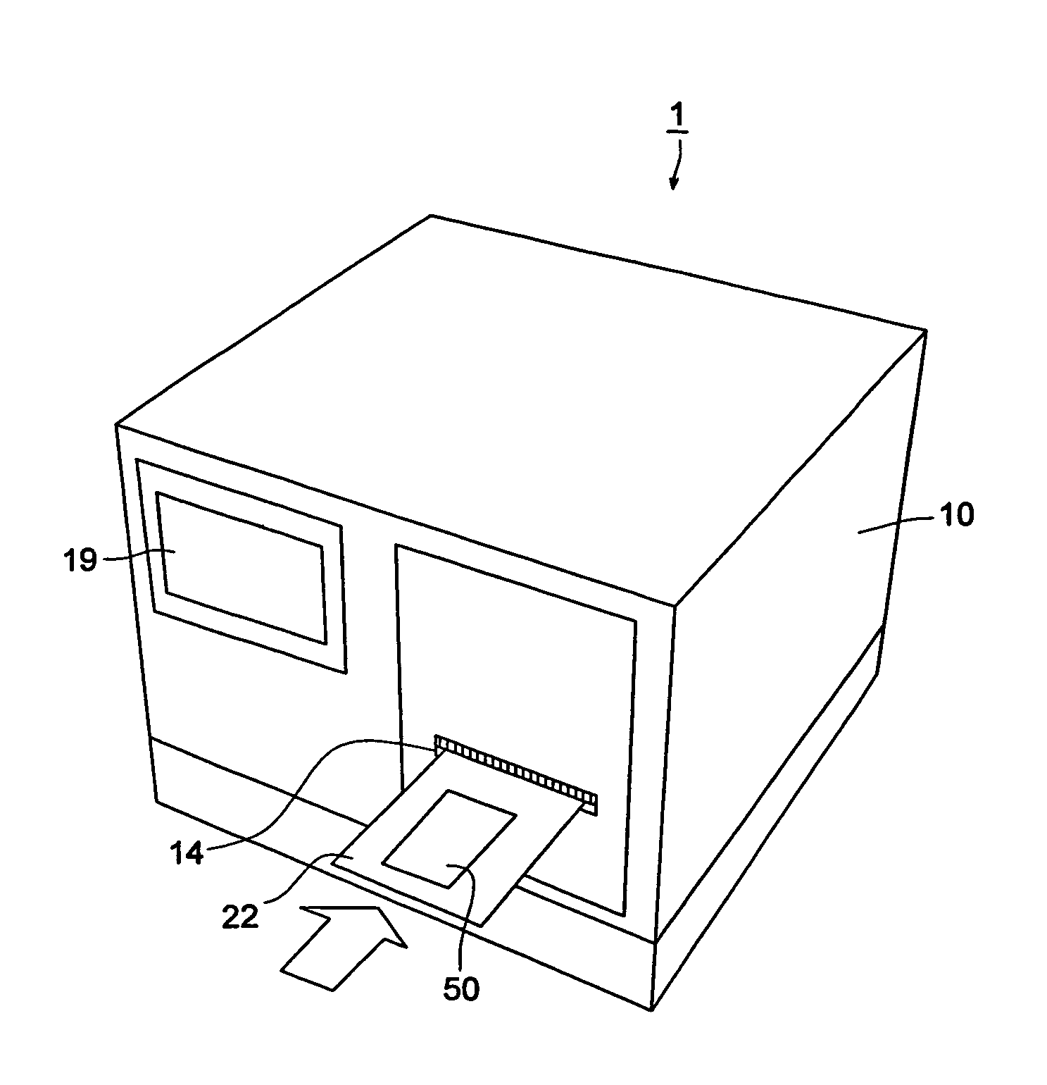
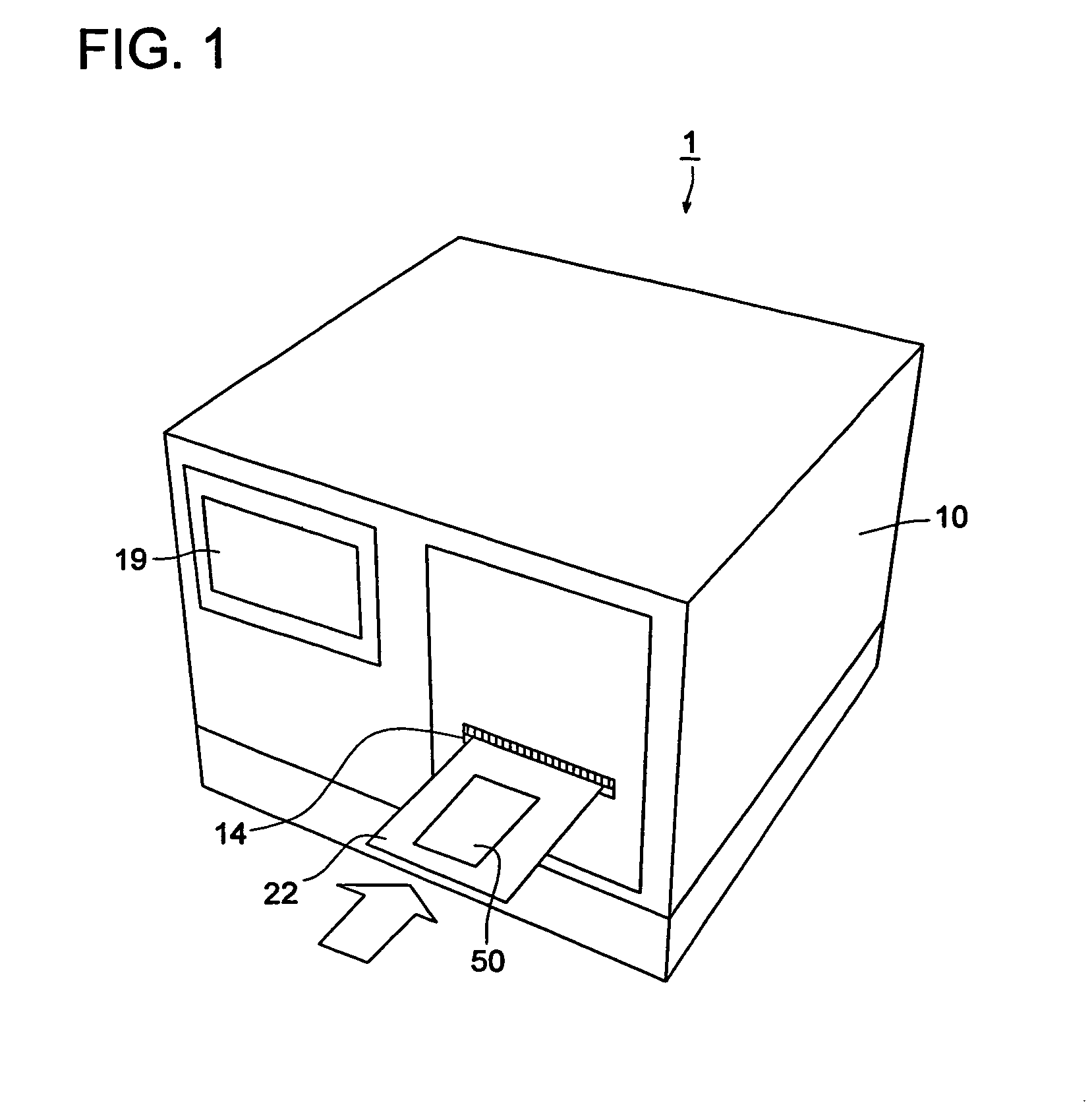
Micro analysis system
a micro-analysis and micro-chip technology, applied in the field of micro-chip testing, can solve the problems of difficult analysis based on reaction as a predetermined purpose, affecting the accuracy of quantitation, gas bubbles in the mixed liquid between a specimen and a reagent, etc., and achieves accurate and correct test, quick heat the mixture
- Summary
- Abstract
- Description
- Claims
- Application Information
AI Technical Summary
Benefits of technology
Problems solved by technology
Method used
Image

Examples
Embodiment Construction
[0052]The present invention includes the following structures and methods.
(Structure 1)
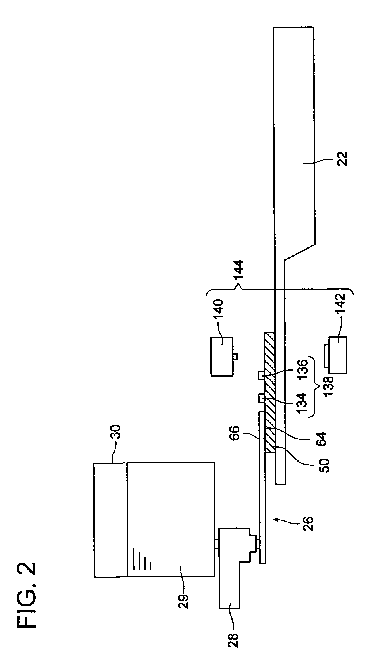
[0053]A micro integrated analysis system, including:[0054]a testing chip that includes:[0055]a pump connecting section provided with flow path openings to communicate with micro pumps;[0056]a micro flow path;[0057]a heat insulating section that is included in a temperature adjusting area for the micro flow path and insulates both end portions of a micro flow path area, to be selectively heated, from heat from a heating side; and[0058]a system main body that includes, at least:[0059]a base main body;[0060]a chip connecting section inside the base main body, having flow path openings to communicate with the testing chip;[0061]a micro pump unit that includes a plurality of micro pumps;[0062]a detection processing device; and[0063]a control device that controls, at least, a function of the micro pump unit and a function of the detection processing device,
wherein,
[0064]the testing chip gets mounted ins...
PUM
| Property | Measurement | Unit |
|---|---|---|
| thermal conductivity | aaaaa | aaaaa |
| width | aaaaa | aaaaa |
| sizes | aaaaa | aaaaa |
Abstract
Description
Claims
Application Information