Energy transformation device

a technology of energy transformation and energy wave, which is applied in the direction of electric generator control, machines/engines, instruments, etc., can solve the problems of energy demand escalating, energy transformation devices cannot produce power cost effectively, and fossil fuels are running out, so as to achieve efficient and cost-effective water wave energy transformation, the effect of little or no environmental impa

Inactive Publication Date: 2011-08-30
GRAY DENNIS
View PDF20 Cites 25 Cited by
  • Summary
  • Abstract
  • Description
  • Claims
  • Application Information

AI Technical Summary

Benefits of technology

[0007]The purpose of this invention is to efficiently and cost effectively transform water wave energy into useful electrical energy with little or no environmental impact. There are numerous advantages of this particular invention in comparison to others conceived before.
[0008]The novelty and effectiveness of this invention is primarily due to many beneficial features. First, maximum available wave power, not partial available power, is extracted and it is extracted on both up and down strokes. Torque arms, acting as levers, multiply the power output. Flywheel gearing ensures power is produced constantly, not intermittently, regardless of ocean waves being sinusoidal and random in nature. The randomness of waves becomes therefore irrelevant. The design is strikingly simple ensuring capital costs are very low and reliability is extremely high. Critical components are 100% protected from oceanic spray keeping maintenance costs negligible. Hundreds of units can be interconnected together without a need for individual, and costly, mooring systems. Unlike offshore wind turbines, where huge permanent structures are driven well into the seabed, hundreds of units simply float and can be interconnected. Many units interconnected is considered an “array”. Mooring of an array can consist of just four wire ropes and anchors at the corners. At approximately yearly intervals, arrays can be towed to shoreside facilities for maintenance. Costly offshore work is therefore eliminated. Units can be spaced close to one another, unlike offshore wind turbines, which concentrates the energy output for a given area occupied. Also unlike wind turbines they are invisible on the horizon at just a few miles out. Finally, with 70% of the world covered by oceans “site availability” is not an issue.
[0009]A novel system for interconnecting energy transformation devices is included herein that utilizes a unique combination of rigid members, flexible members, and pivoting components. This system makes the interconnectivity possible, eliminates the need for individual mooring systems, and allows hundreds of units to be towed via a single tugboat. Towing of many units is desirable since production-line maintenance onshore is far less expensive than offshore maintenance. It also permits the initial installation of many units to be performed in a single step which greatly reduces overall capital investment costs. Finally, with many units connected together it becomes viable to install thrusters and a global positioning system vs. cables and anchors. If thrusters and a global positioning system are utilized then arrays can self-propel themselves around oncoming hurricanes or typhoons.Critical Impact of this Particular Invention
[0010]1. In comparison with wind energy, this invention uses inexpensive steel buoys and torque arms instead of expensive wind turbine blades made from exotic lightweight materials. Although the device essentially has the same gearbox and generator, it eliminates 40%+ of a wind turbine's remaining costs (no tower structure, no tower foundation, no yaw drives, no real estate costs, etc.)
[0013]4. With the novel system for interconnectivity, devices can be mass installed and maintenance can be performed in assembly-line fashion (both are physically impossible with wind turbines).Given the multiple reasons listed above, not just one, this device and interconnect system can logically deliver energy at lower costs than wind energy (5 cents / kwh) and far less than solar energy (20 cents / kwh).

Problems solved by technology

Populations grow exponentially, world economies are expanding, demand for energy is escalating, and fossil fuels are running out.
The difficult part is envisioning how organized and consistent energy can be extracted from what appears to be chaos.
Without addressing all of them an energy transformation device cannot produce power cost effectively.

Method used


Image

  • Energy transformation device
  • Energy transformation device
  • Energy transformation device

Examples


Embodiment Construction

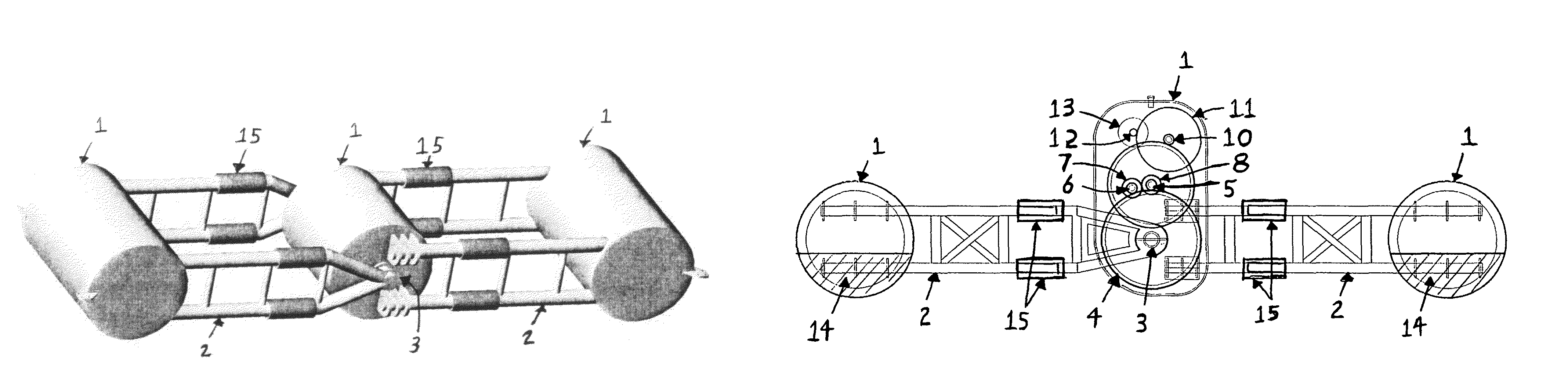
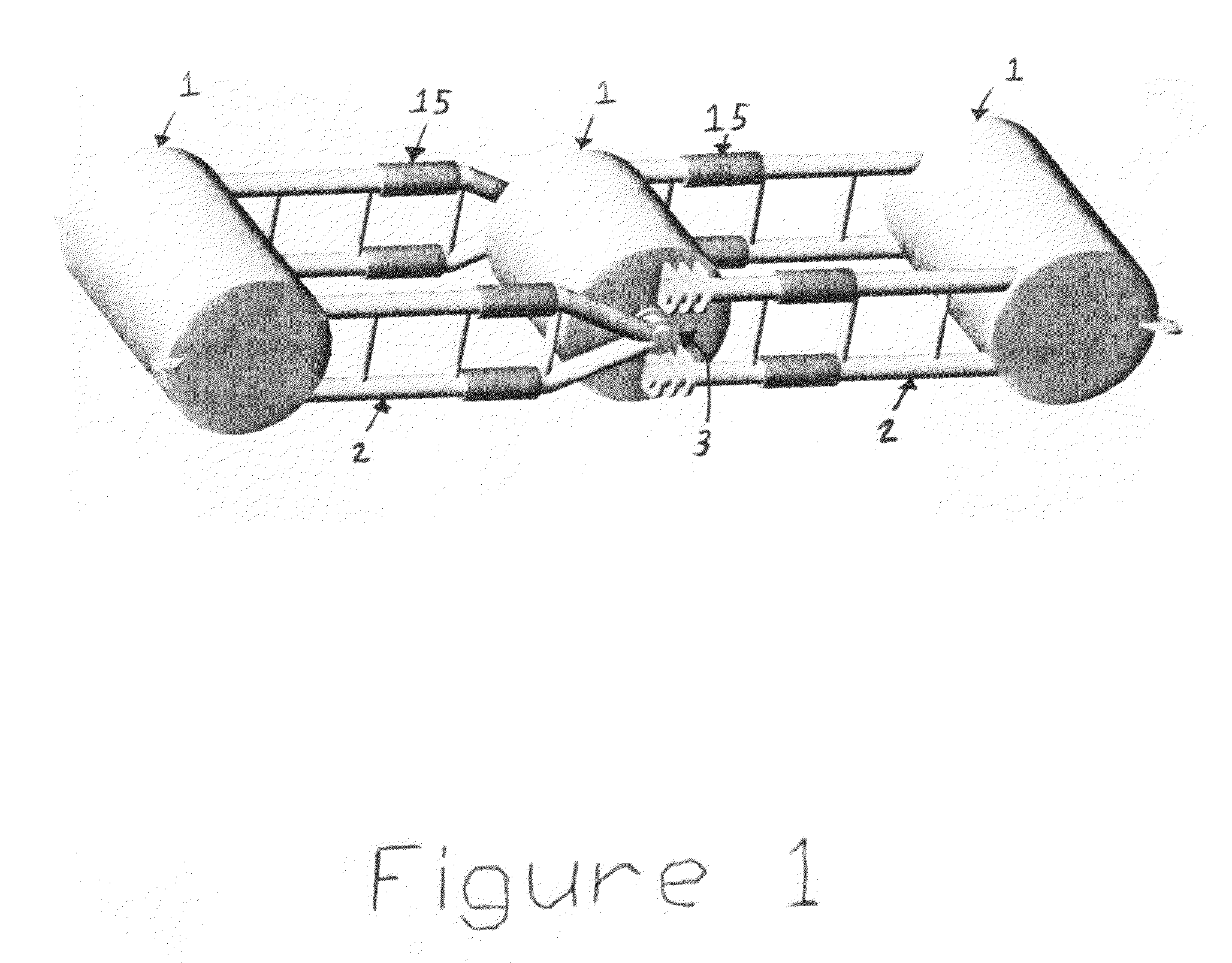
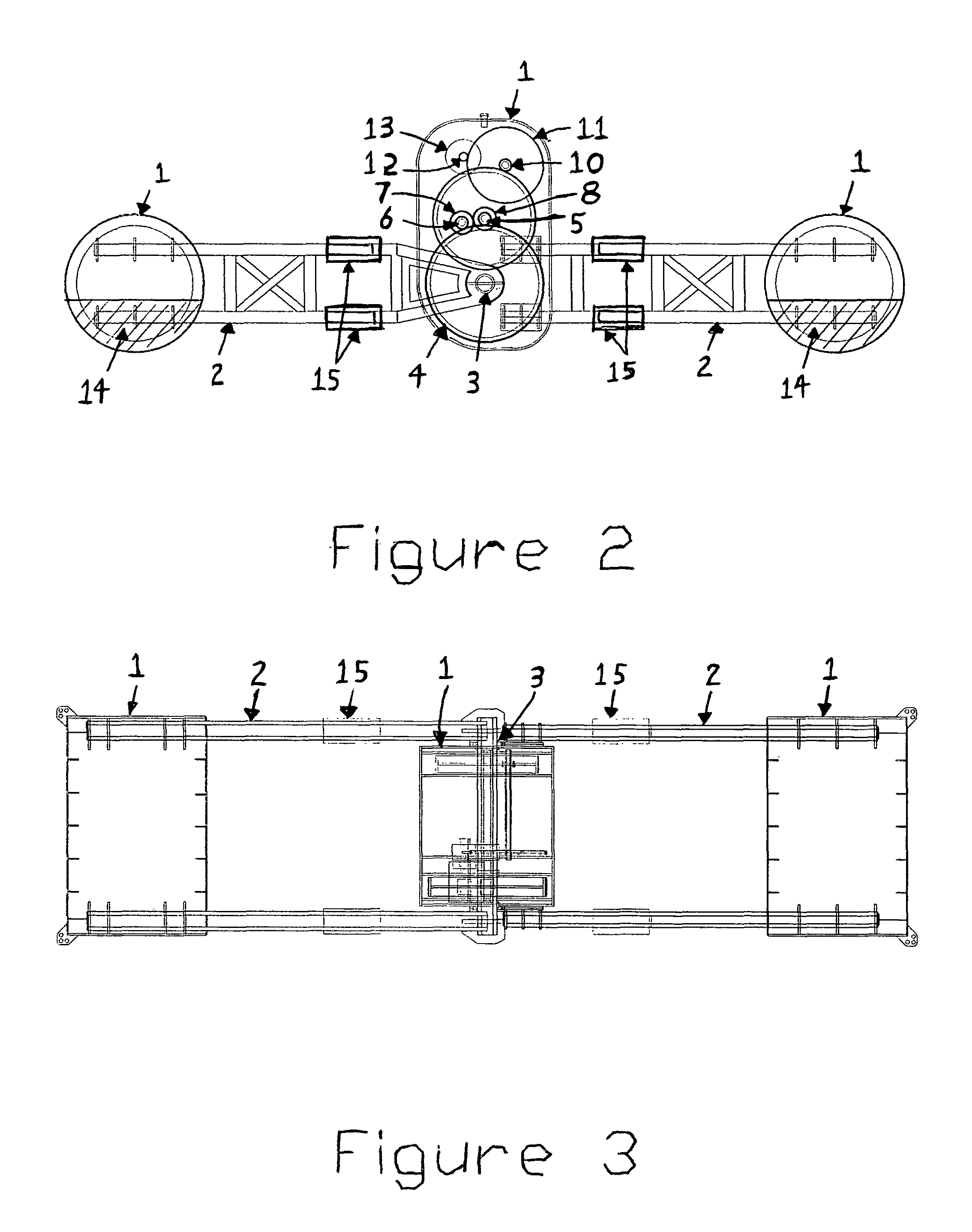
[0020]The figures illustrate a preferred embodiment of this invention. The invention can be designed and scaled for any size waves. A preferred embodiment would primarily be constructed of steel or other suitable marine materials. Components of the device include two or more floats (1) connected by torque arms (2) that pivot relative to one another around a central bushing or bearing (3). The float movements generate torque which rotates gears (4), (5), (6), (7), (8), (9), (10), (11), and (12) which in turns drives a generator (13) at higher speeds for electrical output.

[0021]Note that the height of this invention is unnecessarily tall in this illustration due to the vertical stacking of gears. This was done only to better illustrate gearing concepts. Actual gears in energy transformation devices will likely be more efficiently arranged to shorten the invention's height. Reduced height results in reduced visibility from shore. Painting energy transformation devices ocean blue in col...


PUM


Abstract

This invention is a device for transforming the energy of water waves into useable energy. The device comprises two or more floats, structural members connecting the floats, a means for transferring torque, and one or more generators.

Description

CROSS-REFERENCES TO MOST RELATED APPLICATIONS[0001]U.S. Pat.Nos.Title7,199,481Wave energy conversion system6,857,266Wave energy converter6,812,588Wave energy converter6,772,592Float dependent wave energy device6,791,205Reciprocating generator wave power buoy6,765,307Wave energy converter (WEC)6,392,314Wave energy converter6,226,989Wave energy converter5,027,000Method and apparatus for generating electricity usingwave energy4,412,417Wave energy converter4,359,868Ocean wave energy converter4,345,434Sea and ocean wave energy converter4,258,269Wave power generator4,077,213Wave driven generator20030091393Wave power machine4,078,871Sea wave energy conversionSTATEMENT REGARDING FEDERALLY SPONSORED RESEARCH & DEVELOPMENT[0002]Not Applicable. No others have rights to this patent. Dennis Gray is the sole inventor and the invention was not created under any federally sponsored programs.BACKGROUND OF THE INVENTION[0003]Populations grow exponentially, world economies are expanding, demand for en...

Claims


Application Information

Patent Timeline
Patent Type & Authority Patents(United States)
IPC IPC(8): F03B13/10F03B13/12H02P9/04
CPCF03B13/20Y02E10/38Y02E10/30
Inventor GRAY, DENNIS JOHN
Owner GRAY DENNIS
Why Eureka
Try Eureka