Simplified Wave Energy Device Without One-way Clutches

a wave energy device and one-way clutch technology, applied in water-power plants, mechanical equipment, machines/engines, etc., can solve the problems of wave energy devices, generators that spin too slowly, generators that are too heavy and expensive, etc., to achieve the effect of adding mechanical advantages to power output, low capital cost and high reliability

Inactive Publication Date: 2012-04-12
GRAY DENNIS JOHN
View PDF2 Cites 13 Cited by
  • Summary
  • Abstract
  • Description
  • Claims
  • Application Information

AI Technical Summary

Benefits of technology

[0008]Maximum available wave power, not partial available power, is extracted by this device and it is extracted on both up and down strokes. Torque arms, acting as levers, add mechanical advantage for power output. The refined design ensures that capital costs will be very low and reliability will be extremely high. Critical components are 100% protected from oceanic spray keeping maintenance costs negligible. No reversing gears are utilized and slightly higher gearing ratios are used for significant benefits. The efficiency losses associated with reducing gears is completely eliminated. Reversing gear systems have generators that spin too slowly and are not of large enough diameter. Thus, these generators become too heavy and expensive. Heavy generators inhibit a wave energy device from harnessing energy because the device cannot properly maintain rhythm or resonance with wave motions. Standard gearboxes can and should be utilized instead of reversing gear systems and such gearboxes can come from many suppliers at fairly low prices.
[0009]The use of one-way clutches in wave energy devices presents additional efficiency losses and higher costs. It is better to simply reduce the mass moment of inertia of the gearing and generator so that both gearbox and generator can spin in both directions as waves rise and fall. Multiple hinge points make the device stronger in rough seas and / or quartering seas, enables system redundancy, and enables gearboxes and generators with smaller diameters and lower mass moments of inertia. In combination with reduced mass moments of inertia these wave energy devices should have equipment that accommodates the changing direction of a generator's current flow as waves change from up to down stroke. In essence, sensors would recognize when waves change from up to down motion or when a generator's current direction changes. At these moments the electrical paths would be switched or flip-flopped so that a generator's current is ultimately heading in the preferred direction. Modern electrical equipment can have milli-second response times. In one embodiment, as shown in FIG. 3, the electrical lines are switched at the changing of wave strokes so that the outflow paths remain unchanged.
[0010]Buoys can be flooded and the device temporarily submerged below water level. A system for interconnecting energy transformation devices is included herein. Interconnectivity creates a truly complete system that eliminates the need for many individual mooring lines, eliminates a considerable amount of electrical cable, and it allows many of units to be towed via a single tugboat. Towing of many units is desirable since many units could potentially be installed or removed all at once. Mass towing also enables production-line maintenance at shoreline. Assembly-line maintenance at shoreline is far less expensive and safer than maintenance or repair performed offshore. In essence, while many other arrays are generating power just one array at a time can be brought in for service.

Problems solved by technology

Reversing gear systems have generators that spin too slowly and are not of large enough diameter.
Thus, these generators become too heavy and expensive.
Heavy generators inhibit a wave energy device from harnessing energy because the device cannot properly maintain rhythm or resonance with wave motions.
The use of one-way clutches in wave energy devices presents additional efficiency losses and higher costs.
Buoys can be flooded and the device temporarily submerged below water level.

Method used


Image

  • Simplified Wave Energy Device Without One-way Clutches
  • Simplified Wave Energy Device Without One-way Clutches
  • Simplified Wave Energy Device Without One-way Clutches

Examples


Embodiment Construction

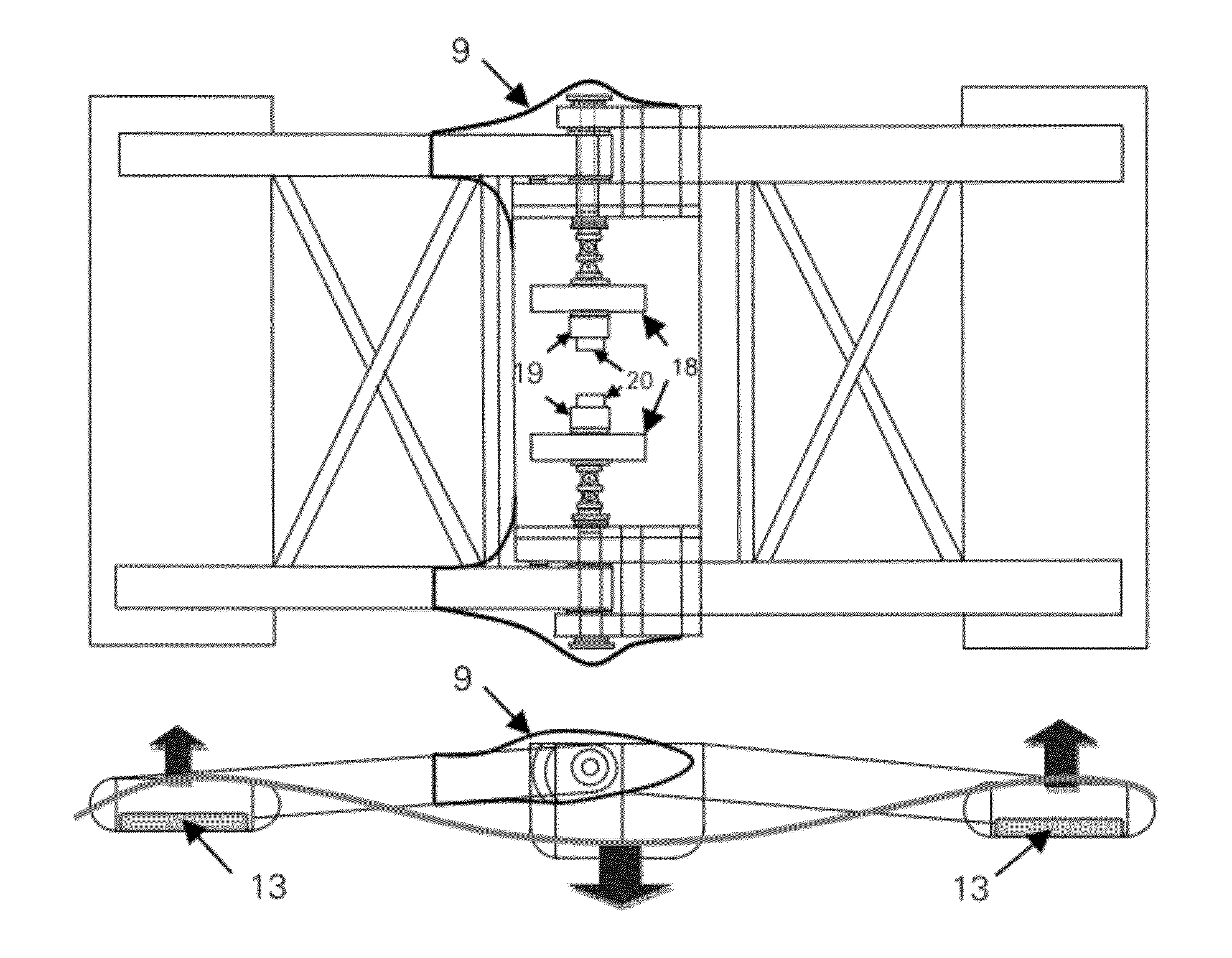
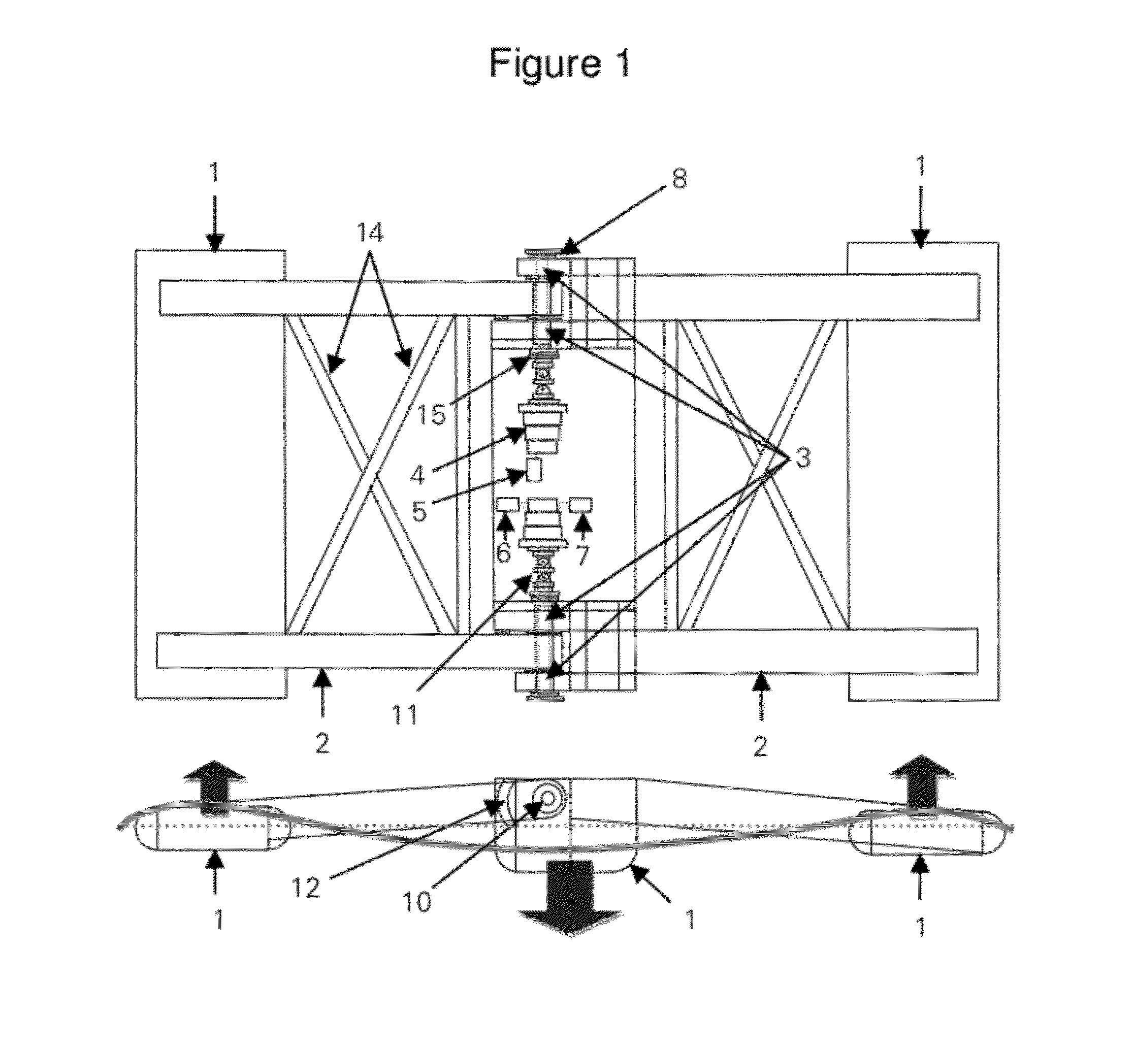
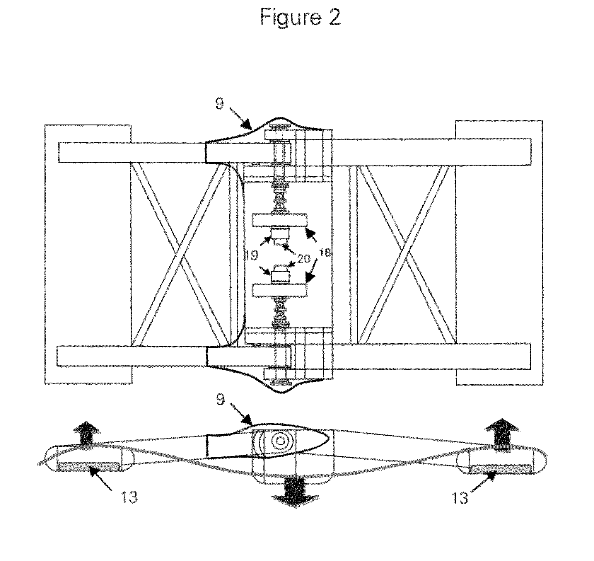
[0016]The invention can be designed and scaled for any size waves. A preferred embodiment would primarily be constructed of steel or other suitable marine materials. Components of the device include two or more buoys (1) connected by torque arms (2) whereby a pivoting motion is permitted at hinge points (3) that have bushing or bearings. The buoy movements generate torque which drive one or more gearboxes (4) which in turns drives one or more generators (5) at higher speeds for electrical output.

[0017]The complex transmission system described in U.S. Pat. No. 7,315,092 is too customized and expensive, reversing gears are not necessary, and reversing gears present unnecessary efficiency losses. Most importantly, the electrical load, or the amount a wave energy device is trying to power, can be controlled such that the moment of inertia of gearboxes and generators can be consumed before a wave reverses direction. For example, electrical load can be electronically increased just as a w...


PUM


Abstract

This invention is a greatly simplified device for transforming the energy of water waves into useable energy. The invention is a device for transforming the energy of water waves into useable energy comprising two or more buoys or buoys, and structural members connecting buoys, whereby motions of buoys relative to one another generates torque, and a means for transferring torque to one or more generators, and a means by which to enable all generator currents to flow in a single beneficial direction. Novel systems for interconnecting such devices are also described herein.

Description

CROSS-REFERENCES TO MOST RELATED APPLICATIONS[0001]Patent orApplication #Title12 / 175,196Energy Transformation Device7,199,481Wave energy conversion system6,857,266Wave energy converter6,812,588Wave energy converter6,772,592Float dependent wave energy device6,791,205Reciprocating generator wave power buoy6,765,307Wave energy converter (WEC)6,392,314Wave energy converter6,226,989Wave energy converter5,027,000Method and apparatus for generating electricityusing wave energy4,412,417Wave energy converter4,359,868Ocean wave energy converter4,345,434Sea and ocean wave energy converter4,258,269Wave power generator4,077,213Wave driven generator20030091393Wave power machine20030110767Method and installation of power generation byocean wave20070164569Ocean energy harvesting system20070164568Wave energy recovery system20070132246Wave energy conversion system20050099010Wave energy conversion system20070180823Wave energy deviceSTATEMENT REGARDING FEDERALLY SPONSORED RESEARCH & DEVELOPMENT[0002]No...

Claims


Application Information

Patent Timeline
Patent Type & Authority Applications(United States)
IPC IPC(8): E02B9/08
CPCE02B9/08Y02E10/38F03B13/20Y02E10/30
Inventor GRAY, DENNIS JOHN
Owner GRAY DENNIS JOHN
Why Eureka
Try Eureka