Forward-flyback converter with active-clamp circuit

a forward-flyback converter and active-clamp technology, which is applied in the direction of dc-dc conversion, power conversion systems, climate sustainability, etc., can solve the problems of low efficiency and low voltage across the secondary winding of the flyback sub-circuit, and achieve the improvement of the drawback of insufficient resonant current, the effect of reducing unnecessary element power loss and high conversion efficiency

Active Publication Date: 2011-08-30
DELTA ELECTRONICS INC
View PDF10 Cites 52 Cited by
  • Summary
  • Abstract
  • Description
  • Claims
  • Application Information

AI Technical Summary

Benefits of technology

[0008]It is therefore an object of the present invention to provide an active-clamp forward-flyback converter for load variation in a wide range and having relatively higher conversion efficiencies under both the heavy and light loads. Under the heavy load condition, the ZVS scheme of the active-clamp flyback converter is employed to improve the drawback of insufficient resonant current in the conventional active-clamp forward-flyback converter. Under the light load condition, the time interval in which the resonant current turns from negative into positive is prolonged to assure that the main switch could achieve ZVS. Meanwhile, the diode of the flyback sub-circuit is designed to be reverse biased such that this sub-circuit is inactive and therefore the unnecessary element power losses are reduced.
[0009]It is therefore another object of the present invention to design the flyback sub-circuit at the secondary side to operate in continuous conduction mode (CCM) and the cathode of its diode to connect to the positive terminal of the output capacitor. As a result, magnetic reset energy of the transformer could be directly transmitted to the output capacitor and the load side via the secondary winding of the flyback sub-circuit to facilitate the energy conversion.
[0010]It is therefore another object of the present invention to increase a flywheeling diode in the forward sub-circuit at the secondary side such that the slope of the output inductor current is not influenced by the clamp capacitor voltage. Moreover, the output inductor is designed to operate in discontinuous conduction mode (DCM). Therefore, the duty ratio D will automatically decrease when the load becomes light, and the clamp capacitor voltage also becomes decreased correspondingly. When the load becomes further light, the clamp capacitor voltage is reduced so that the voltage across the secondary winding of the flyback sub-circuit is not high enough to forward bias the diode of the flyback sub-circuit. At the moment, the flyback sub-circuit is inactive so as to decrease the unnecessary element power losses. As a result, the efficiency of the present invention under the light load condition could be improved. Meanwhile, the starting point of this mechanism could be determined by properly arranging the turns ratio of the primary and secondary windings. In general, the starting point is chosen at the load condition with too low efficiency.
[0011]It is therefore another object of the present invention to let the DCM forward sub-circuit keep supplying the output power under the light load condition, so that the present invention is equivalent to an active-clamp DCM forward converter. The flyback sub-circuit does not influence the process in which the resonant current turns from negative into positive; thus, the slope of the resonant current is relatively gradual. The time in which the resonant current remains negative will be prolonged, and this feature facilitates to realize ZVS of the main switch under the light load condition.
[0012]It is therefore another object of the present invention to cause the reverse biased voltages of the diodes to be lower than those of the conventional active-clamp forward-flyback converter such that lower voltage rated diodes could be chosen. Meanwhile, due to the DCM operation, the output inductance is far smaller than that of a conventional active-clamp forward-flyback converter. Therefore, the volume and cost of the output inductor could be reduced so as to have cost-effectiveness.

Problems solved by technology

When the load becomes further light, the clamp capacitor voltage is reduced so that the voltage across the secondary winding of the flyback sub-circuit is not high enough to forward bias the diode of the flyback sub-circuit.
In general, the starting point is chosen at the load condition with too low efficiency.

Method used


Image

  • Forward-flyback converter with active-clamp circuit
  • Forward-flyback converter with active-clamp circuit
  • Forward-flyback converter with active-clamp circuit

Examples


Embodiment Construction

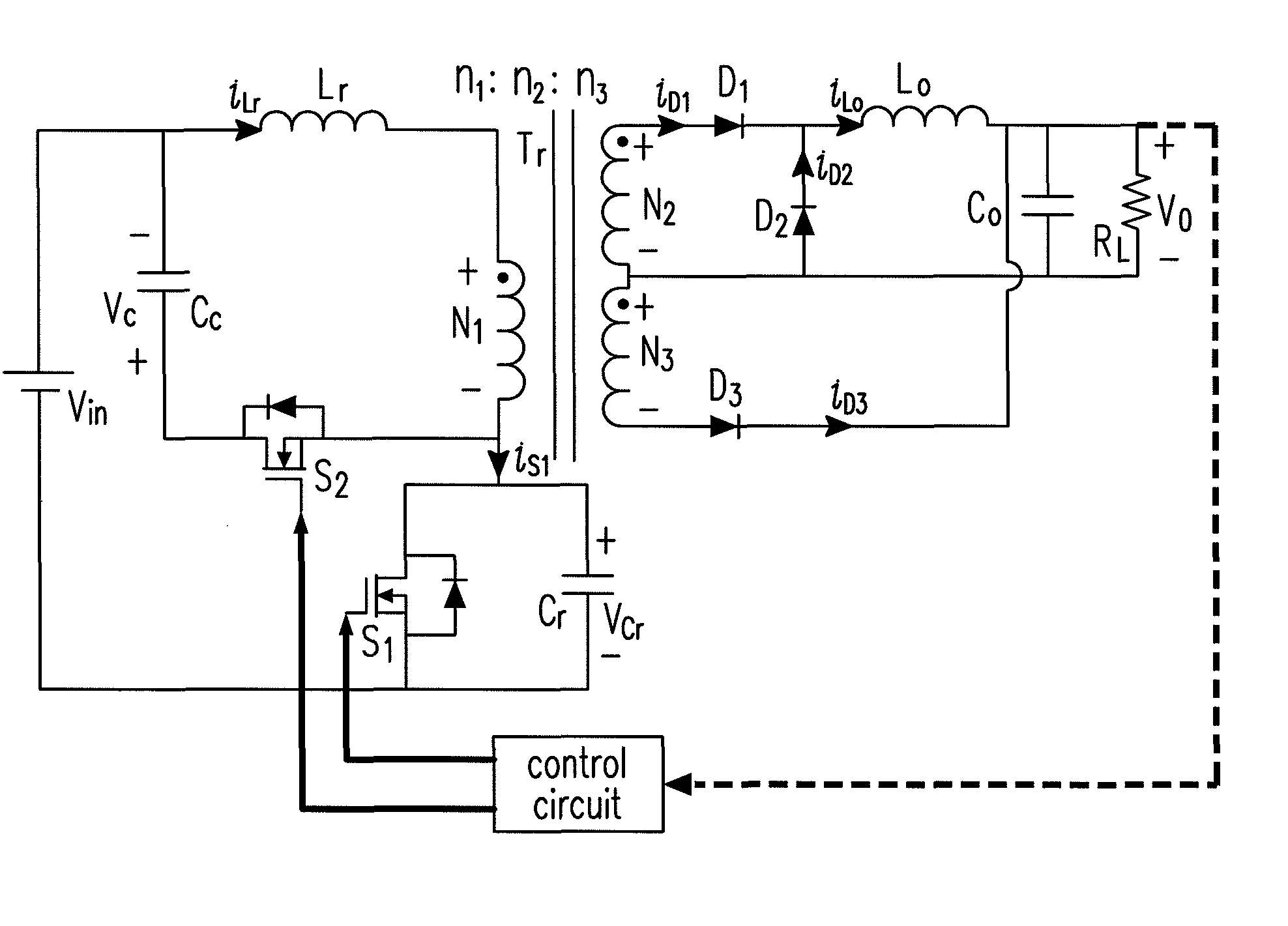
[0023]FIG. 3 shows a circuit diagram of a forward-flyback converter with the buck-boost type active-clamp circuit according to the first preferred embodiment of the present invention, it includes a forward-flyback converter with the buck-boost type active-clamp circuit and a control circuit. Through the control circuit, an output voltage regulation and a rapid response function under dynamic load variation could be achieved. The polarities of each voltage amount and the direction of each current amount of the active-clamp forward-flyback converter are defied in FIG. 3. With the use of transformer Tr, the input energy could be transmitted continuously to the output terminal via the secondary windings N2 and N3 of the transformer Tr and the flyback sub-circuit could be deactivated under the light load condition. The transformer Tr includes a primary winding N1, a first secondary winding N2 and a second secondary winding N3, and the turns ratio of the windings N1, N2 and N3 is: n1:n2:n...


PUM


Abstract

The present invention discloses a forward-flyback converter with active-clamp circuit. The secondary side of the proposed converter is of center-tapped configuration to integrate a forward circuit and a flyback circuit. The flyback sub-circuit operating continuous conduction mode is employed to directly transfer the reset energy of the transformer to the output load. The forward sub-circuit operating discontinuous conduction mode can correspondingly adjust the duty ratio with the output load change. Under the heavy load condition, the mechanism of active-clamp flyback sub-circuit can provide sufficient resonant current to facilitate the parasitic capacitance of the switches to be discharged to zero. Under the light load condition, the time interval in which the resonant current turns from negative into positive is prolonged to ensure zero voltage switching function. Meanwhile, the flyback sub-circuit wherein the rectifier diode is reverse biased is inactive in order to further reduce the power losses.

Description

FIELD OF THE INVENTION[0001]The present invention relates to isolated DC / DC converters and AC / DC converters. More particularly, the present invention relates to a forward-flyback converter having an active-clamp circuit. The major characteristics of this power conversion technique are transferring the input power to the secondary side continuously, having relatively better conversion efficiency for load variation in a wide range and relatively better cost-effectiveness.BACKGROUND OF THE INVENTION[0002]Since the functions of the electronic products on the market are reinforced, the power supply is demanded to provide relatively greater output energy as a response. At the same time, the products are demanded to have smaller volume and lighter weight. These trends form two requirements towards the power converters: raising the power density and improving the conversion efficiency. Based on these two requirements, a large amount of active-clamp forward-flyback converters and their deriv...

Claims


Application Information

Patent Timeline
Patent Type & Authority Patents(United States)
IPC IPC(8): H02H7/122
CPCH02M3/33569Y02B70/1433Y02B70/10H02M3/01
Inventor LIU, YEN-MING
Owner DELTA ELECTRONICS INC
Why Eureka
Try Eureka