Inertial measurement system with self correction

a self-correction, measurement system technology, applied in the direction of instruments, navigation instruments, calibration apparatus, etc., can solve the problems of gps not being available indoors, magnetometers themselves being subject to errors, and much higher-performance angular rate sensors are, of course, much more expensiv

Active Publication Date: 2011-08-30
LORD CORP
View PDF33 Cites 49 Cited by
  • Summary
  • Abstract
  • Description
  • Claims
  • Application Information

AI Technical Summary

Problems solved by technology

A much higher-performance angular rate sensor is, of course, much more expensive, and GPS is often not available indoors and in outdoor locations between tall buildings.
While a magnetic compass (magnetometers) has often been used as a reference to stabilize compass heading measurements, magnetometers have themselves been subject to error because of strong and unpredictable distortions of Earth's geomagnetic field, particularly in indoor environments.

Method used


Image

  • Inertial measurement system with self correction
  • Inertial measurement system with self correction
  • Inertial measurement system with self correction

Examples


Embodiment Construction

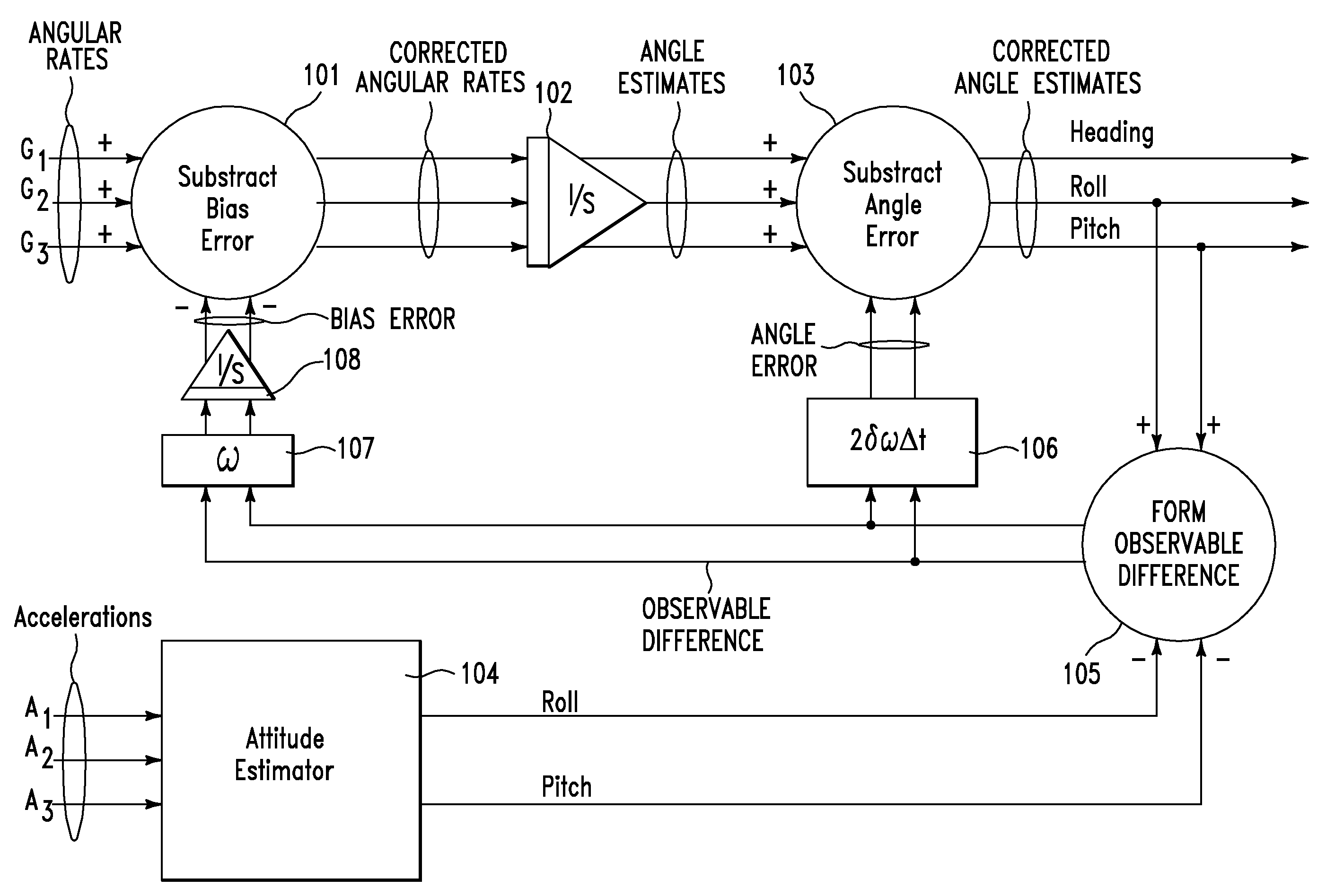
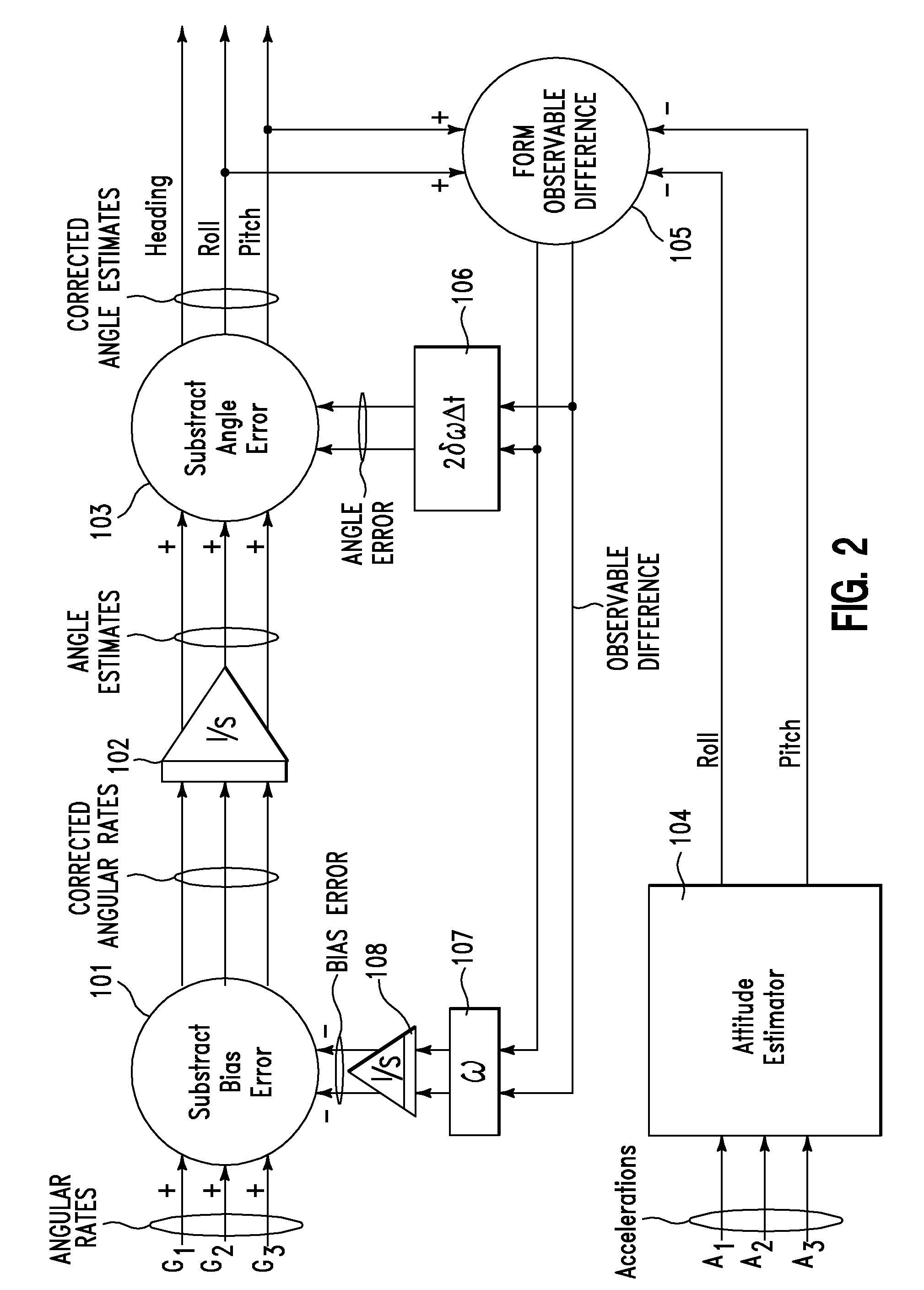
[0026]The present applicant recognized a solution that overcomes the problem identified in the prior art with determining compass heading angular rate sensor bias error with accelerometers. This system provides an inertial measurement unit that automatically corrects for compass heading angular rate sensor bias error and improves navigation accuracy without resort to magnetometers, GPS, or the expensive angular rate sensors specified in the prior art. The system of the present patent application uses only an accelerometer for measuring and correcting for compass heading angular rate sensor bias error.

[0027]The bias of an angular rate sensor is the output of that sensor when the angular rate input is zero, that is when it is not actually rotating. Accurate knowledge of the bias allows correction of raw sensor output. Bias of an angular rate sensor is typically measured during a calibration procedure that provides bias calibration coefficients. Correction of the raw sensor output with...


PUM


Abstract

A method of navigation includes providing an angular rate sensor and a direction-of-gravity reference. The method also includes determining bias error of the angular rate sensor about a vertical axis based on data substantially from the angular rate sensor and from the direction-of-gravity reference. In one embodiment, the first angular rate sensor is moved from a first position around a substantially horizontal axis to a second position around the substantially horizontal axis. The first angular rate sensor provides angular rate data for attitude at the first position and for compass heading at the second position. Data from the first angular rate sensor and from the direction-of-gravity reference is processed with a program for determining a bias error correction for the first angular rate sensor while the first angular rate sensor is in the first position. Bias error correction determined while the first angular rate sensor is in the first position is used to correct angular rate of the first angular rate sensor while the first angular rate sensor is in the second position.

Description

RELATED PATENT APPLICATIONS AND PRIORITY[0001]This application claims priority of now expired Provisional Patent Application 61 / 004,118, filed Nov. 23, 2007, incorporated herein by reference.FIELD[0002]This patent application generally relates to navigation and to orientation sensing. More particularly it relates to inertial measurement systems. Even more particularly it relates to an inertial measurement system that corrects itself for bias error.BACKGROUND[0003]Personnel location tracking in areas where GPS signals are intermittent or unavailable has been an important consideration for military, firefighting, and consumer markets. Several researchers have reported on foot-borne micro-electromechanical sensors (MEMS) for personnel navigation. These sensors may include accelerometers, angular rate sensors, and magnetometers.[0004]Schemes for navigation that include MEMS angular rate sensors have long been known that provide for correction of pitch and roll angular rate sensor bias e...

Claims


Application Information

Patent Timeline
Patent Type & Authority Patents(United States)
IPC IPC(8): G01C25/00G06F19/00
CPCG01C21/16G01C25/005G01C21/188
Inventor CHURCHILL, DAVID L.
Owner LORD CORP
Why Eureka
Try Eureka