
System and method for network interfacing

a network interface and network technology, applied in the field of interfaces for networks, can solve the problems of large power and space requirements of systems, large program size (typically greater than 100 kb), and large memory operation, and achieve the effect of reducing the number of memory operations

Inactive Publication Date: 2011-08-30
AVAGO TECH INT SALES PTE LTD
View PDF32 Cites 148 Cited by
  • Summary
  • Abstract
  • Description
  • Claims
  • Application Information

AI Technical Summary

Benefits of technology

The present invention provides systems and methods for network interfacing, including data centers and servers. The invention allows for the handling of multiple types of traffic over a single fabric using a single layer 2 (L2) connector of the server. The invention also allows for accessing storage systems, clusters, and networks over a single fabric in a data center. The technical effects of the invention include improved efficiency and flexibility in network interfacing and improved performance and reliability in data centers.

Problems solved by technology

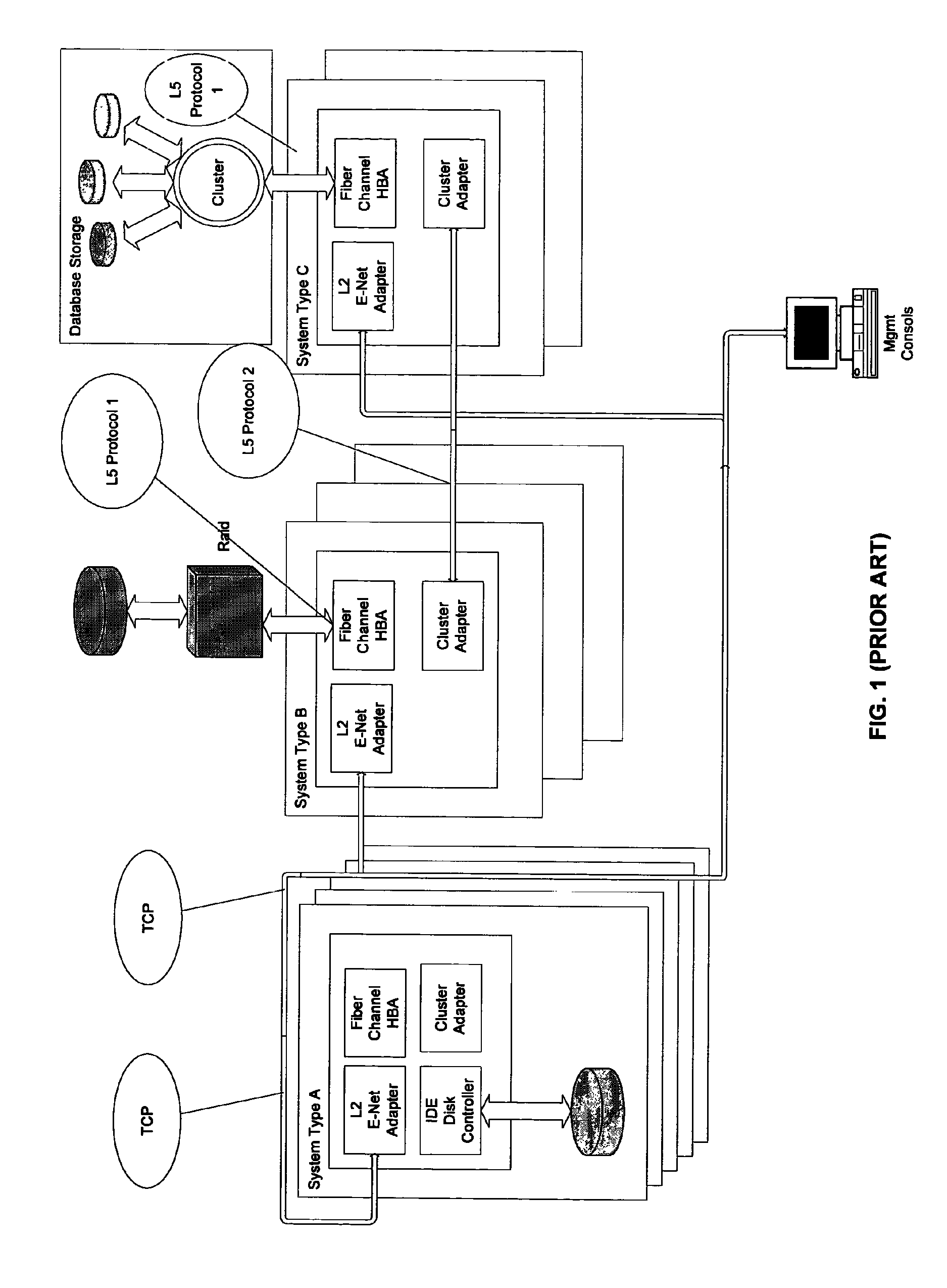
Such requirements produce systems with substantial power and space requirements.
These programs are large (typically greater than 100 KB) and computationally quite intensive.
Furthermore, these programs expect large amounts of memory to operate.
As density requirements for servers increase, as evidenced by the use of Server Blades in servers, the space required for the three different types of adapters is becoming less available.
The problem is further exacerbated since additional adapters may be used to provide fault tolerance or load balancing.
The cost of managing three different fabrics and the toll on the information technology (IT) departments which must provide personnel trained in multiple technologies are substantial burdens to bear.
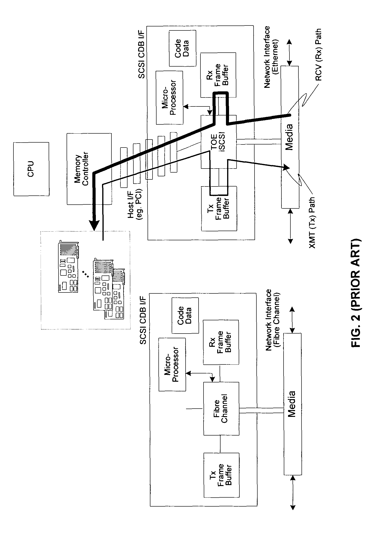
This places the burden of implementation of the complete conversion from an application memory down to the wire protocol on the adapter.
Until recently, TCP / IP was not considered a feasible solution as it runs in software which generally involves more CPU overhead and high latencies.
Furthermore, TCP / IP does not guarantee all segments are received from the wire in the order that they were transmitted.
Furthermore, the conventional server may still employ a proprietary network interface which cannot be coupled to the L4 / L5 Ethernet switch.

Method used


Image

  • System and method for network interfacing
  • System and method for network interfacing
  • System and method for network interfacing

Examples


Embodiment Construction

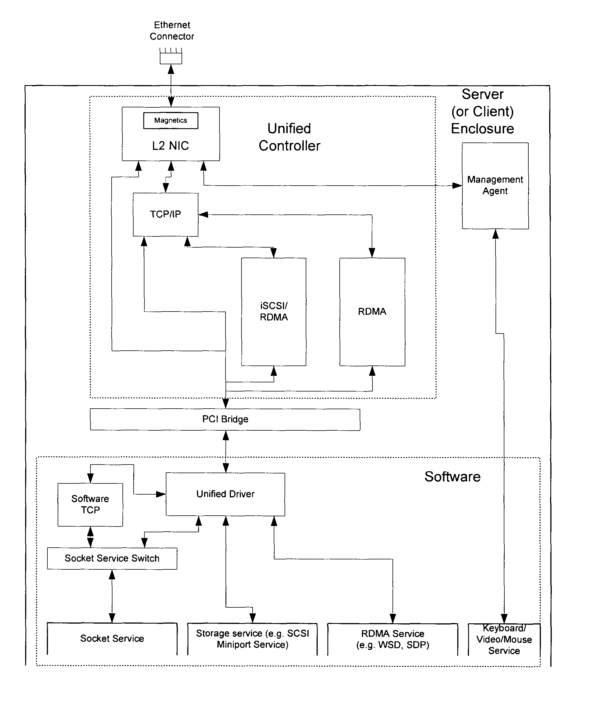
[0033]Aspects of the present invention may be found in, for example, systems and methods that provide network interfacing. Some embodiments according to the present invention provide a device that can handle all the communication needs of a computer (e.g., a server, a desktop, etc.) The device may use protocols that are running on transmission control protocol / Internet protocol (TCP / IP) such as, for example, TCP / IP / Ethernet. Storage traffic may be handled using an Internet small computer system interface (iSCSI) protocol which relies on TCP as the transport and may employ a TCP offload engine to accelerate its operation. Clustering traffic may be handled using a remote direct memory access (RDMA) protocol that runs on top of TCP. Clustering may be combined into the same device as TCP offload. Further convergence may be achieved if the iSCSI protocol uses the RDMA fabric.

[0034]Some embodiments according to the present invention may provide for the convergence of three fabrics into a ...


PUM


Abstract

Systems and methods that network interface are provided. In one embodiment, a data center may be provided that may include, for example, a first tier, a second tier and a third tier. The first tier may include, for example, a first server. The second tier may include, for example, a second server. The third tier may include, for example, a third server. At least one of the first server, the second server and the third server may handle a plurality of different traffic types over a single fabric.

Description

CROSS-REFERENCE TO RELATED APPLICATIONS / INCORPORATION BY REFERENCE[0001]This application makes reference to, claims priority to and claims benefit from U.S. Provisional Patent Application Ser. No. 60 / 477,279, entitled “System and Method for Network Interfacing in a Multiple Network Environment” and filed on Jun. 10, 2003; U.S. Provisional Patent Application Ser. No. 60 / 478,106, entitled “System and Method for Network Interfacing” and filed on Jun. 11, 2003; U.S. Provisional Patent Application Ser. No. 60 / 408,617, entitled “System and Method for TCP / IP Offload” and filed on Sep. 6, 2002; U.S. Provisional Patent Application Ser. No. 60 / 407,165, entitled “System and Method for TCP Offload” and filed on Aug. 30, 2002; U.S. Provisional Patent Application Ser. No. 60 / 456,265, entitled “System and Method for TCP Offload” and filed on Mar. 30, 2003; U.S. Provisional Patent Application Ser. No. 60 / 456,260, entitled “System and Method for Handling Out-of-Order Frames” and filed on Mar. 20, 20...

Claims


Application Information

Patent Timeline
Patent Type & Authority Patents(United States)
IPC IPC(8): G06F15/16G06F15/173
CPCG06F13/102G06F13/4027H04L69/163H04L29/06095H04L69/22H04L69/18H04L69/161G06F2213/0024H04L69/16
Inventor ELZUR, URIFAN, FRANKIELINDSAY, STEVEN B.MCDANIEL, SCOTT S.
Owner AVAGO TECH INT SALES PTE LTD
Learn More