Coaxial cable connector

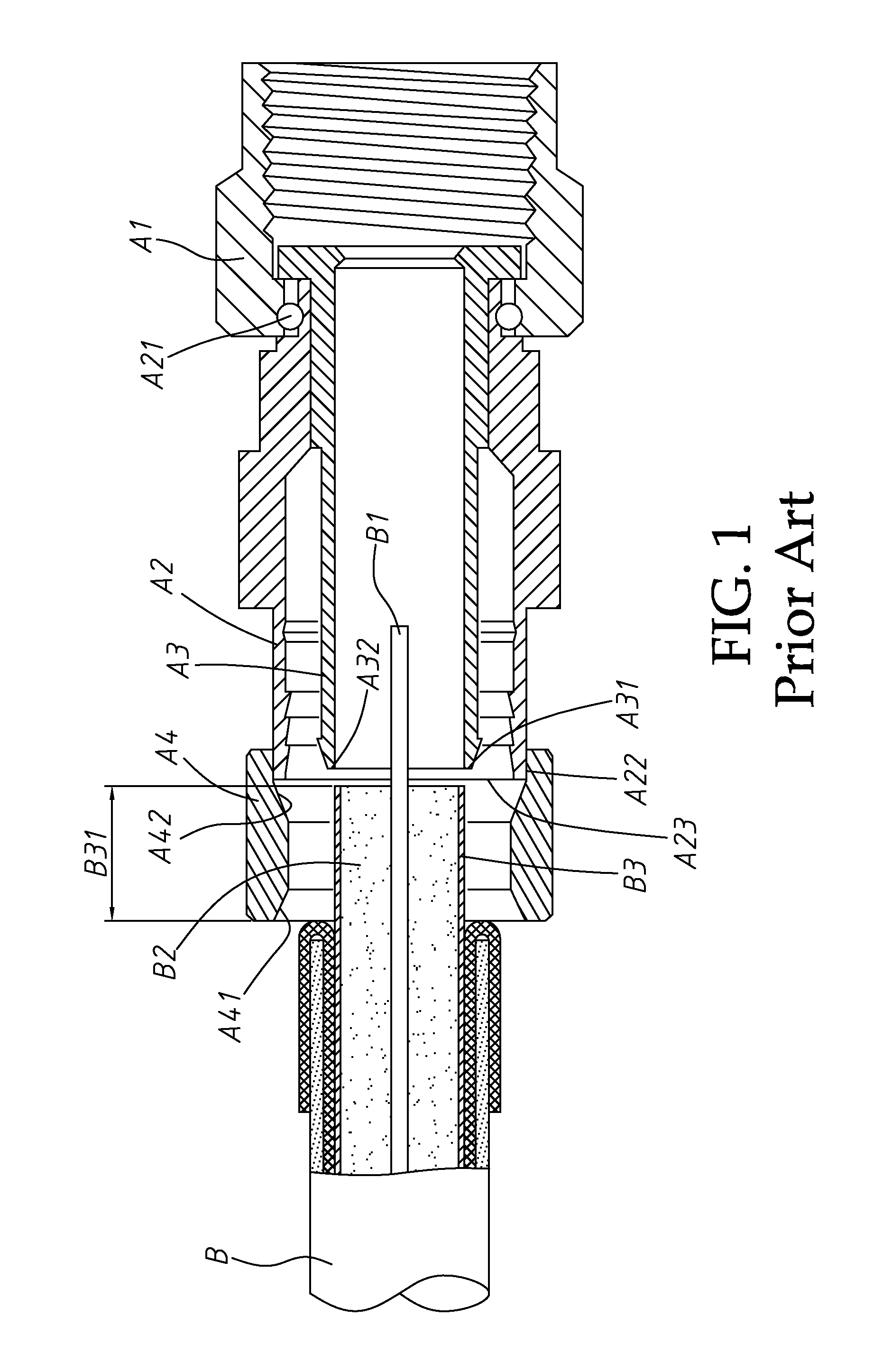
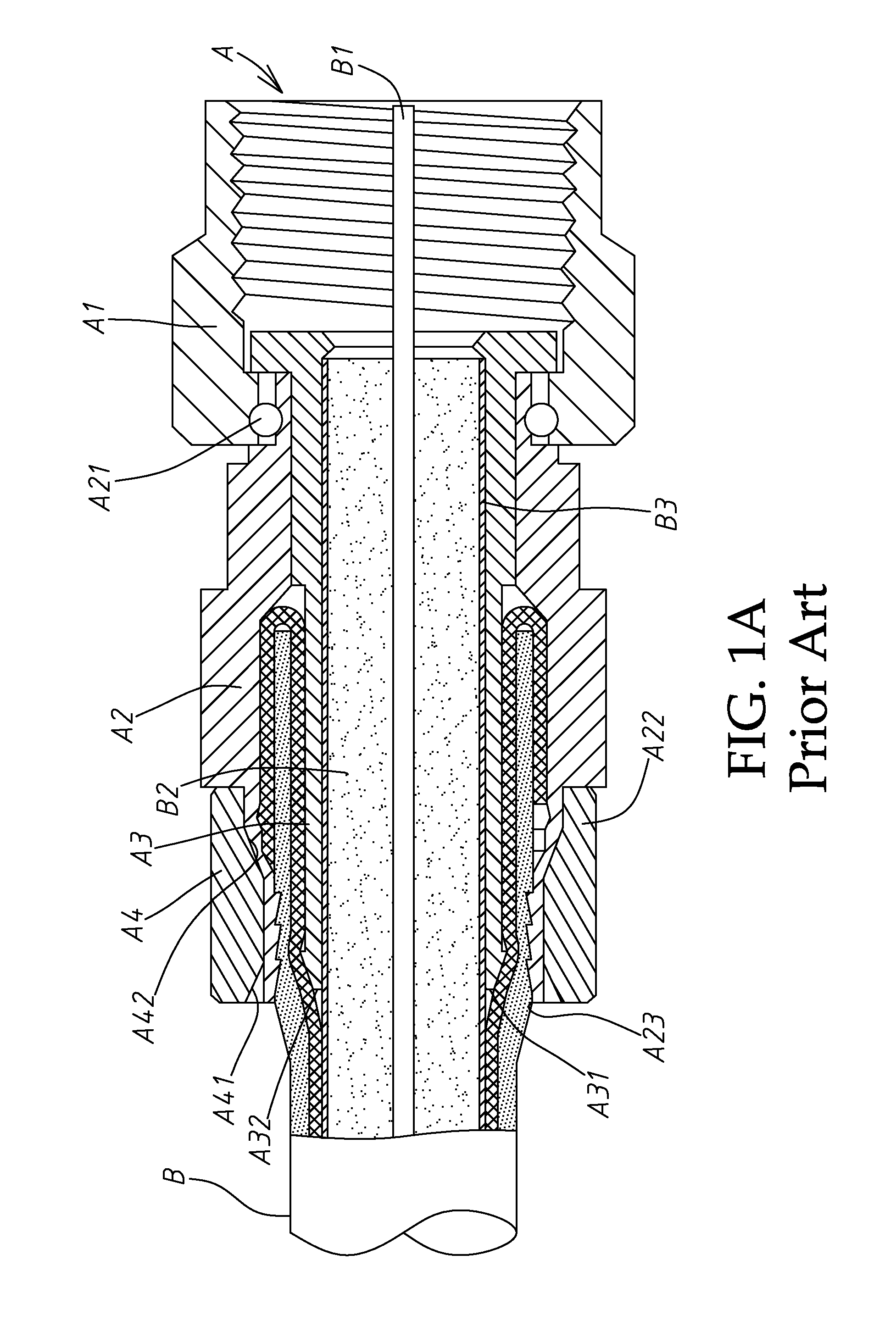
a technology of coaxial cable and connector, which is applied in the direction of electrical apparatus, connection, coupling device connection, etc., can solve the problems of plastic body shell, limited application of this design of cable end connector, and oxidation soon

Inactive Publication Date: 2011-09-06
LU YUEH CHIUNG
View PDF4 Cites 42 Cited by
  • Summary
  • Abstract
  • Description
  • Claims
  • Application Information

AI Technical Summary

Benefits of technology

[0015]The present invention has been accomplished under the circumstances in view. It is therefore the main object of the present invention to provide a coaxial cable connector assembled with a coaxial cable consisting of a center conductor, surrounded by an insulation spacer, surrounded by an aluminum foil, surrounded by a braided outer conductor, surrounded by a protective plastic covering. The protective plastic covering of the coaxial cable been stripped off subject to a predetermined length to expose the braided outer conductor, the exposed braided outer conductor been turned backwardly onto the protective plastic covering to expose the insulation spacer and the aluminum foil and to leave a predetermined length of the bare aluminum foil outside the protective plastic covering for installation in the coaxial cable connector. The coaxial cable connector comprises a screw nut having an inner thread for threading onto an outer thread of a mating member; an inner tube mounted in one end of the screw nut, the inner tube comprising a barbed unit extending around the periphery of a left end thereof remote from the screw nut and a foil insertion hole defined in the left end; a body shell surrounding the inner tube, the body shell comprising an axial hole, a clamping portion surrounding the axial hole and a stop flange extending around the periphery at one end of the clamping portion; a barrel sleeved onto one end of the body shell beyond the clamping portion and defining with the body shell a crimping distance before installation of the coaxial cable in the coaxial cable connector, the barrel comprising a left orifice for entrance of the coaxial cable connector, a packing hole defined therei

Problems solved by technology

However, when the aforesaid cable end connector A is assembled with a coaxial cable B, the plastic body shell A2 is partially exposed to the weather (see FIG. 1A) and will become aged and oxidized soon.
Therefore, the application of this design of cable end connector is limited.
1. The plastic body shell A2 is partially exposed to the outside between the screw nut A1 and the metal barrel A4. When the cable end connector A is used outdoor, the plastic body shell A2 will become aged and oxidized soon under the effect of the sun, rain and wind, and rainwater may leak in between the cable end connector A and the coaxial cable B, affecting signal transmission stability and quality. If a metal body shell is used to substitute for the plastic body shell A2, the crimping operation during installation of the cable end connector will become difficult. Therefore, this design of cable end connector is not well invited in the market.
2. A long distance is left between the aluminum foil insertion hole A32 on the left end of the inner tube A3 and the left orifice A41 of the metal barrel A4. This distance is approximately equal to the length of the bare aluminum foil B31 of the coaxial cable B (or even longer), as shown in FIG. 1. Thus, it is difficult to insert the insulation spacer B2 and aluminum foil B3 of the coaxial cable B into th

Method used


Image

  • Coaxial cable connector
  • Coaxial cable connector
  • Coaxial cable connector

Examples


Embodiment Construction

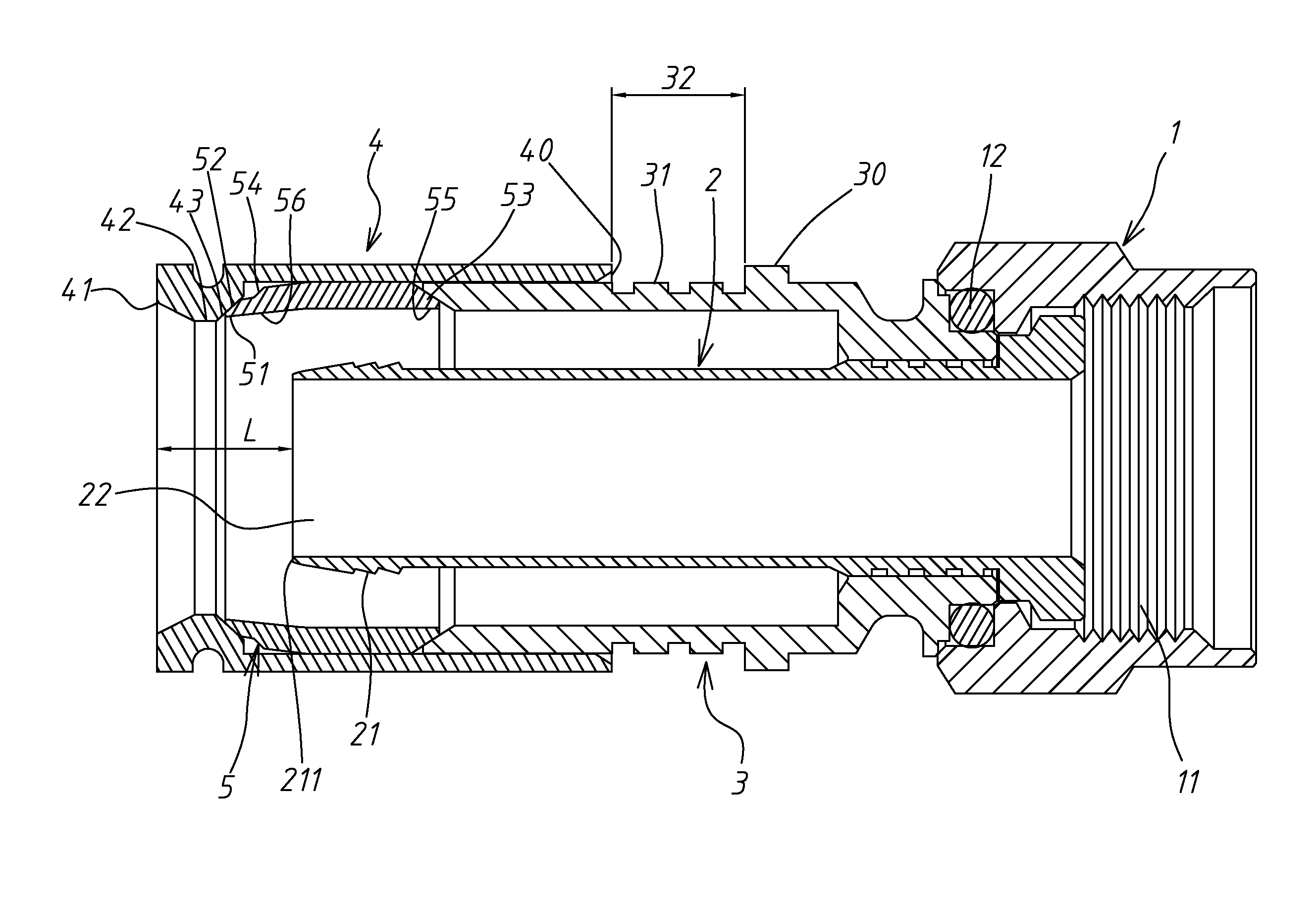
[0033]Referring to FIGS. 3˜5, a coaxial cable connector 100 in accordance with the present invention is shown comprising a screw nut 1, an inner tube 2, a body shell 3, a barrel 4 and a plastic bushing 5.

[0034]The coaxial cable connector 100 is assembled with a coaxial cable B consisting of a center conductor B1, surrounded by an insulation spacer B2, surrounded by an aluminum foil B3, surrounded by a braided outer conductor B4, surrounded by a protective plastic covering B5. The braided outer conductor B4 can be a standard, tri-shield or quad-shield design.

[0035]Referring to FIG. 5 again, the screw nut 1 has an inner thread 11 for threading onto an outer thread of a mating member (not shown); the inner tube 2 is mounted in one end of the screw nut 1; the body shell 3 surrounds the inner tube 2, having a clamping portion 31 and a stop flange 30 extending around the periphery at one end of the clamping portion 31; the inner tube 2 has a barbed unit formed of at least one, for example...


PUM


Abstract

A coaxial cable connector suitable for assembly with one of a series of coaxial cables having one same specification and different wire outer diameters is disclosed to use a plastic bushing for compressing by a barrel to wrap about the coaxial cable and compress an inner tube against the aluminum foil and insulation spacer of the coaxial cable, protecting the coaxial cable against weather and extending the lifespan. A short distance is left between the aluminum foil insertion hole on the left end of the inner tube and the left orifice of the barrel, facilitating insertion of the insulation spacer and aluminum foil of the coaxial cable without causing damage.

Description

BACKGROUND OF THE INVENTION[0001]1. Field of the Invention[0002]The present invention is coaxial cable connectors and more particularly to such a coaxial cable connector that fits a series of coaxial cables having one same specification and different wire outer diameters.[0003]2. Description of the Related Art[0004]In current television market, cable TV is the mainstream. Cable TV signal is transmitted to a television of a subscriber through a coaxial cable. Coaxial cable is not limited to cable TV application, it can also be used in any of a variety of other fields for signal transmission. For two-way high-frequency transmission, a coaxial cable is extended from an outdoor place to the inside of a house and then connected to a TV or TV splitter through a coaxial cable connector. This coaxial cable connector is adapted for connecting a coaxial cable to a mating connector at the TV or TV splitter.[0005]To fit different signal transmission quality requirements, the braided outer condu...

Claims


Application Information

Patent Timeline
IPC IPC(8): H01R9/05
CPCH01R9/0524H01R13/622
Inventor LU, YUEH CHIUNG
Owner LU YUEH CHIUNG
Why Eureka
Try Eureka