Marine drive with break-away mount

a technology of drive and mount, which is applied in the direction of marine propulsion, vessel construction, propulsive elements, etc., can solve the problems of reducing torsional strength, unsatisfactory use of weaker constituent materials for threaded fasteners b>306/b>, and small outer diameter section at b>322/b> cannot tolerate installation torqu

Active Publication Date: 2011-09-06
BRUNSWICK CORPORATION
View PDF88 Cites 37 Cited by
  • Summary
  • Abstract
  • Description
  • Claims
  • Application Information

AI Technical Summary

Problems solved by technology

However, a very narrow (very small outer diameter) section at 322 cannot tolerate installation torque.
Using a weaker constituent material for threaded fastener 306 is not desirable because such weaker material will be subject to excessive elongation, and hence the threaded fastener may stretch rather than break-away.
As such neck diameter decreases, the tor

Method used


Image

  • Marine drive with break-away mount
  • Marine drive with break-away mount
  • Marine drive with break-away mount

Examples


Embodiment Construction

Background Description

[0031]The following description of FIGS. 1-11 is taken from incorporated U.S. Pat. No. 7,234,983.

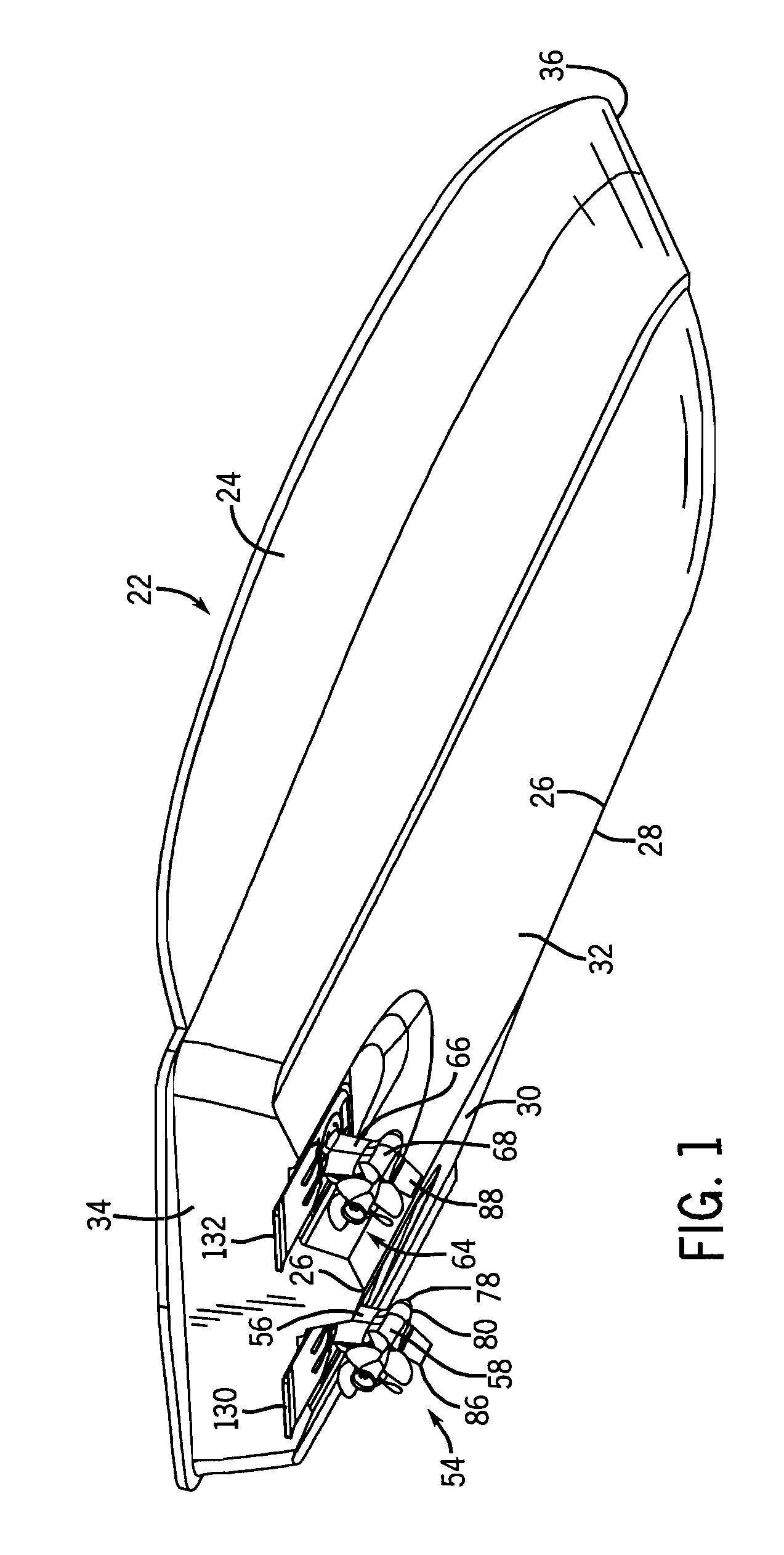
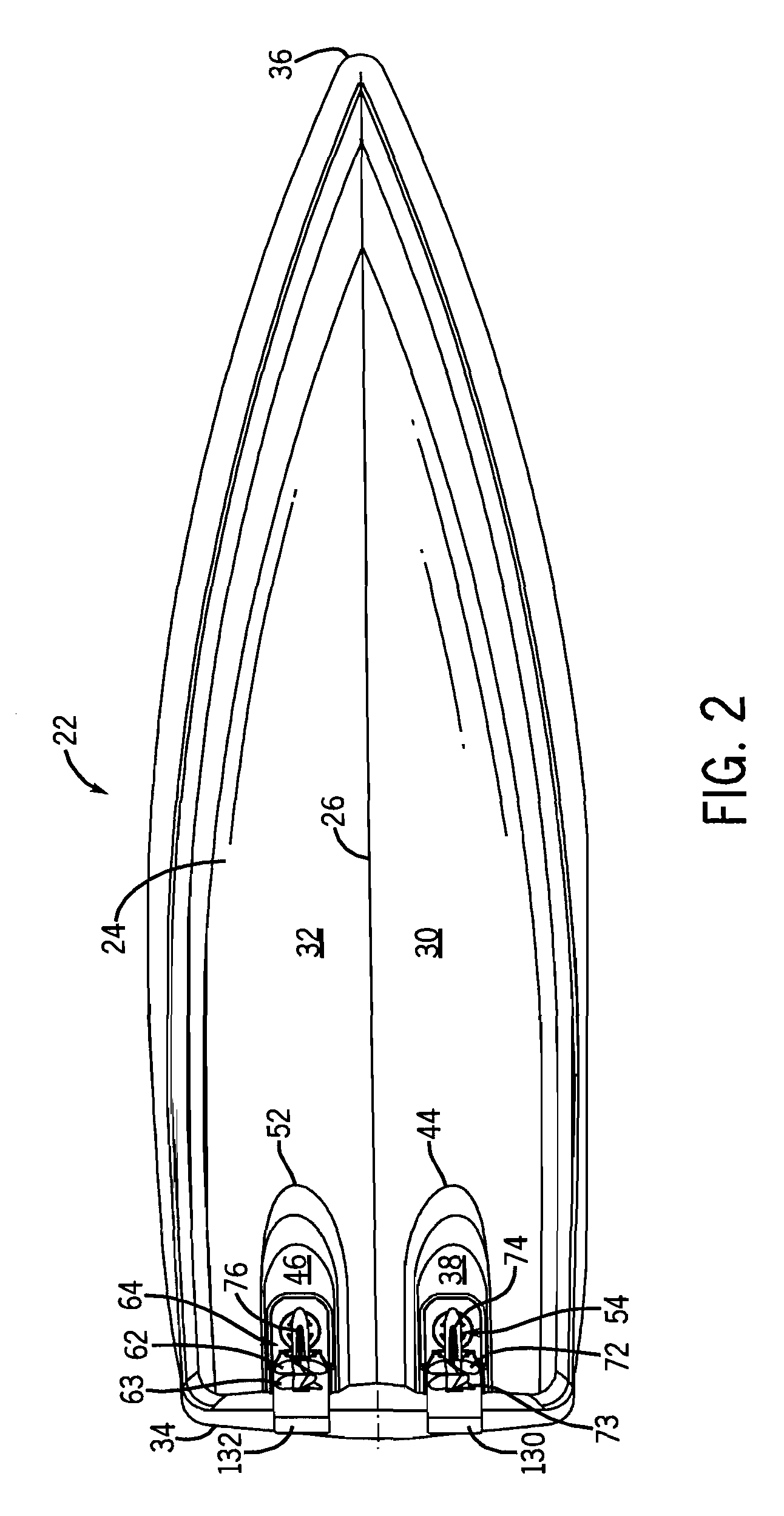
[0032]FIGS. 1-4 show a marine vessel and drive combination. Marine vessel 22 includes a hull 24 having a longitudinally extending keel 26 having a lower reach 28. The hull has port and starboard lower hull surfaces 30 and 32, respectively, extending upwardly and laterally distally oppositely from keel 26 in V-shaped relation, FIG. 4. Hull 24 extends forwardly from a stern 34 to a bow 36.

[0033]A port tunnel 38, FIG. 2, is formed in port lower hull surface 30. Port tunnel 38 has a top 40, FIG. 4, spaced above an open bottom 42 at port lower hull surface 30. Port tunnel 38 opens aft at stern 34 and extends forwardly therefrom and has a closed forward end 44 aft of bow 36. A starboard tunnel 46 is formed in starboard lower hull surface 32. Starboard tunnel 46 has a top 48 spaced above an open bottom 50 at starboard lower hull surface 32. Starboard tunnel 46 opens aft at...


PUM


Abstract

A marine drive has a break-away mount mounting first and second sections of the drive and breaking-away in response to a given underwater impact against the second section to protect the first section and the vessel.

Description

BACKGROUND AND SUMMARY[0001]The invention relates to marine drives and to marine vessel and drive combinations.[0002]Marine drives as well as marine vessel and drive combinations are known in the prior art. The present invention arose during continuing development efforts directed to a marine drive for propelling a marine vessel, including a marine propulsion device extending from the vessel and having a water-engaging propulsor for propelling the vessel through a body of water, the marine drive having a first section mounted to the vessel, and a second section supporting the water-engaging propulsor for rotation. The invention also arose during continuing development efforts related to commonly owned: U.S. Pat. No. 7,188,581; U.S. Pat. No. 7,234,983; co-pending U.S. patent application Ser. No. 11 / 586,191, filed Oct. 25, 2006, a continuation-in-part of the '581 patent and a continuation-in-part of the '983 patent; co-pending U.S. patent application Ser. No. 11 / 677,720, filed Feb. 22...

Claims


Application Information

Patent Timeline
IPC IPC(8): B63H5/125
CPCB63B39/061B63H5/125B63H5/10B63H2005/1256
Inventor DAVIS, RICHARD A.CREECH, DAVID T.MIHELICH, MICHAEL P.CUMMINGS, JAY LEE
Owner BRUNSWICK CORPORATION
Why Eureka
Try Eureka