Energy and emission responsive routing for vehicles

a technology for energy and emission, applied in the direction of process and machine control, instruments, navigation instruments, etc., can solve the problems of significant environmental damage, vehicle exhaust generation, and/or consumption of non-renewable fuel resources, and achieve the effect of faster total travel time and faster total travel tim

Active Publication Date: 2011-09-06
KYNDRYL INC
View PDF19 Cites 20 Cited by
  • Summary
  • Abstract
  • Description
  • Claims
  • Application Information

AI Technical Summary

Benefits of technology

[0005]Service methods are also provided, wherein a service provider deploys a computational device infrastructure configured to determine the plurality of different routes for travel and to identify the vehicle as either the internal combustion engine vehicle type or a hybrid vehicle type configured to generate operative energy through a regenerative braking energy component. The computational device infrastructure is further configured to determine that traveling a first route will result in a faster total travel time and that traveling a second route will cause more breaking by the vehicle relative to traveling the first route, and responsively recommend the first route over the second route to an operator of an identified internal combustion engine vehicle type and recommend the second route over the first route to an operator of an identified hybrid vehicle type as a function of the more braking determination.

Problems solved by technology

The worldwide use of automobiles, trucks and other internal combustion engine vehicles is believed to cause significant environmental damage.
Although use of an on-board no-emission green energy source to propel the hybrid generally results in little or no direct harmful emissions or non-renewable fuel source use, hybrids must still generally use their combustion engine power sources as well in order to accomplish some trips, thus still resulting in the generation of vehicle exhaust and / or the consumption of non-renewable fuel resources.

Method used


Image

  • Energy and emission responsive routing for vehicles
  • Energy and emission responsive routing for vehicles
  • Energy and emission responsive routing for vehicles

Examples


Embodiment Construction

[0014]For convenience the Detailed Description of the Invention has the following sections:

[0015]I. General Description; and

[0016]II. Computerized Implementation.

I. General Description

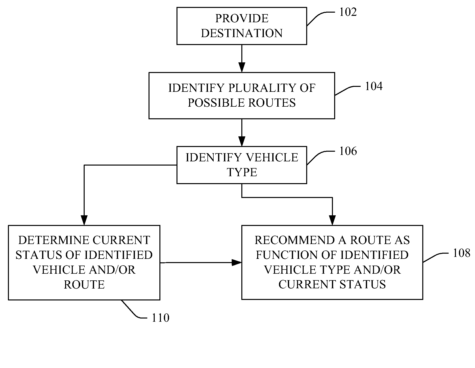
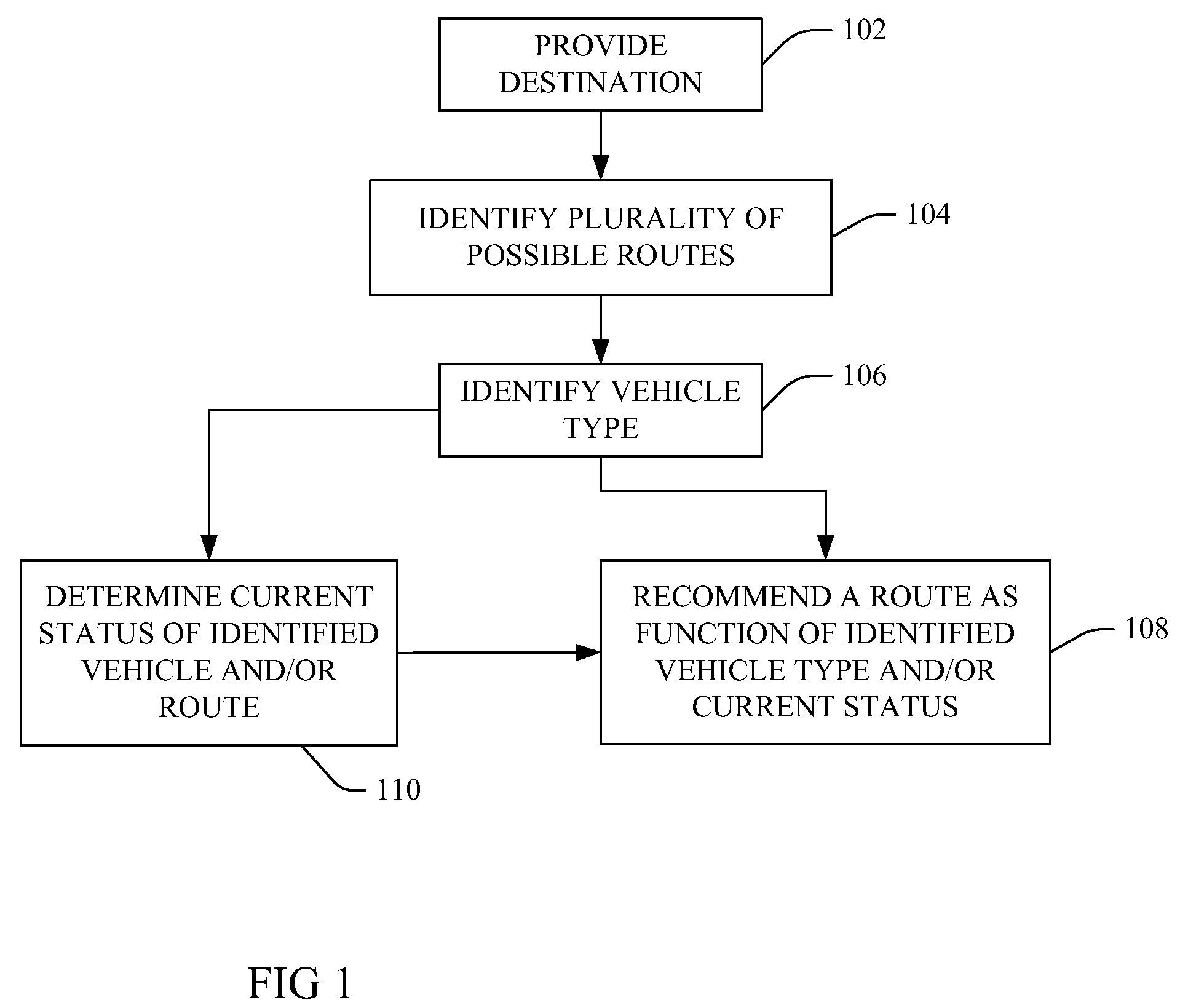
[0017]FIG. 1 is a flow chart illustrating a method and system for vehicle route planning as a function of vehicle type according to the present invention. At 102 a destination is provided, and at 104 a plurality of different possible routes are identified for travel by a vehicle from a trip origin (e.g. a specified origin or a current location of the vehicle, in some examples as determined by global positioning satellite (GPS) system component) to the destination. At 106 the type of vehicle is identified, and more particularly as either an internal combustion engine vehicle type or a hybrid vehicle type. At 108 a route of the plurality of routes is recommended to an operator of the identified vehicle as a function of the identified type, wherein a route recommended to an identified internal combustion ...


PUM


Abstract

Methods, including service methods, articles of manufacture, systems, articles and programmable devices are provided for vehicle route planning as a function of vehicle type. A plurality of different routes for travel by a vehicle from a trip origin to a destination is determined, and the vehicle identified as either an internal combustion engine vehicle type or a hybrid vehicle type. A programmable device is caused to recommend a route of the determined plurality of routes to an operator of the identified vehicle as a function of the identified vehicle type, wherein a route recommended to the identified internal combustion engine vehicle type is different from a route recommended to the identified hybrid vehicle type. In some examples, identifying the vehicle as configured to generate operative energy through a regenerative braking energy component results in recommending a route will cause more breaking over a faster route.

Description

FIELD OF THE INVENTION[0001]The present invention generally describes methods, systems and devices for decreasing fuel energy use and associated emissions of a vehicle by providing route planning as a function of vehicle fuel energy and non-fuel energy usage characteristics.BACKGROUND OF THE INVENTION[0002]The worldwide use of automobiles, trucks and other internal combustion engine vehicles is believed to cause significant environmental damage. In one estimate, 590 million passenger vehicles operating worldwide consume an average of 550 gallons of gasoline per year, resulting in a worldwide consumption of 324,500,000,000 gallons of gasoline per year. It is also estimated that each vehicle exhausts on a yearly basis an average of 80 pounds of smog-causing hydrocarbons, 606 pounds of carbon monoxide, 41 pounds of nitrogen oxide (which causes acid rain and contributes to smog) and 10,000 pounds of carbon dioxide (which is believed to cause global climate change).[0003]Hybrid electric ...

Claims


Application Information

Patent Timeline
Patent Type & Authority Patents(United States)
IPC IPC(8): G01C21/32G06F19/00
CPCG01C21/3469G06Q30/018
Inventor BOSS, GREGORY J.HAMILTON, II, RICK A.O'CONNELL, BRIAN M.PICKOVER, CLIFFORD A.WALKER, KEITH R.
Owner KYNDRYL INC
Why Eureka
Try Eureka