Electrical connector

a technology of electrical connectors and connector bodies, applied in the direction of coupling device details, coupling device connections, electric discharge lamps, etc., can solve the problems of structural instability, structural damage or contact error between conducting terminals, and the limited bandwidth of dvi interface devices for big scale lcds, so as to enhance the connection stability between the connector body and the metal shielding shell, the effect of minimizing friction

Active Publication Date: 2011-09-13
CHANT SINCERE
View PDF2 Cites 31 Cited by
  • Summary
  • Abstract
  • Description
  • Claims
  • Application Information

AI Technical Summary

Benefits of technology

[0011]The present invention has been accomplished to provide an electrical connector, which eliminates the drawbacks of the aforesaid prior art design. According to one aspect of the present invention, the electrical connector comprises a connector body and a metal shielding shell. The connector body comprises an electrically insulative base block, an electrically insulative front extension portion forwardly extended from the front side of the electrically insulative base block for insertion into an external electrical connector, and a plurality of conducting terminals mounted in the electrically insulative base block and the electrically insulative front extension portion. The electrically insulative base block has a front vertical stop wall abutted to the electrically insulative front extension portion and adapted for stopping against the front edge of the plug of an inserted external electrical connector, and a locating notch located on the middle part of the front vertical stop wall. The metal shielding shell surrounds the connector body, comprising a front insertion port for the insertion of an external electrical connector and a positioning block downwardly protruded from the top wall near the rear side thereof and engaged into the locating notch of the electrically insulative base block of the connector body. Further, the electrically insulative base block comprises a rear vertical stop wall disposed at the top side thereof opposite to the front vertical stop wall. Further, the metal shielding shell comprises two rear locating strips bilaterally extended from the top wall thereof and stopped against the rear vertical stop wall of the electrically insulative base block. When an external electrical connector is inserted into the metal shielding shell to connect the connector body, the front edge of the plug of the inserted external electrical connector will be stopped against the front vertical stop wall of the electrically insulative base block and the positioning block of the metal shielding shell that is positioned in the locating notch and kept in flush with the front vertical stop wall. Further, the locating strips are stopped against the rear vertical stop wall of the electrically insulative base block, the connection stability between the connector body and the metal shielding shell is enhanced, assuring structural reliability.
[0012]Further, the metal shielding shell comprises two bonding strips respectively downwardly extended from two opposite sidewalls thereof and respectively terminating in a respective flat ground pin at the bottom side for bonding to the ground contacts of a circuit board by SMT (surface mount technology). Because the inwardly curved bonding strips are disposed at the bottom side of the metal shielding shell, bonding the flat ground pins of the bonding strips to the ground contacts of a circuit board does not cause the solder material to flow along the inner surfaces of the flat ground pins into the inside of the metal shielding shell. Thus, the flat ground pins of the bonding strips can be positively bonded to the ground contacts of the circuit board, avoiding accidental disconnection of flat ground pins of the bonding strips from the ground contacts of the circuit board during insertion of an external electrical connector into the metal shielding shell, or jam of the inserted external electrical connector due to accumulation of excessive solder material (solder paste) in the metal shielding shell.
[0013]Further, the metal shielding shell comprises two raised portions respectively located on an inner surface of each of two opposite sidewalls thereof for friction engagement with an inserted external electrical connector. During insertion of an external electrical connector into the metal shielding shell, the two raised portions of the metal shielding shell are respectively stopped against the two opposite lateral sides of the plug of the inserted external electrical connector, minimizing friction between the external electrical connector and the inside wall of the metal shielding shell, and assuring insertion stability of the inserted external electrical connector.

Problems solved by technology

However, DVI interface devices simply provide a limited bandwidth for big scale LCD display device.
This pressure may cause the engagement between the retaining members B2 of the metal shielding shell B and the retaining grooves A3 of the electrically insulative body A to be loosened, resulting in structural instability, structural damage or contact error between the conducting terminals A2 and the inserted external electrical connector.

Method used


Image

  • Electrical connector
  • Electrical connector
  • Electrical connector

Examples


Embodiment Construction

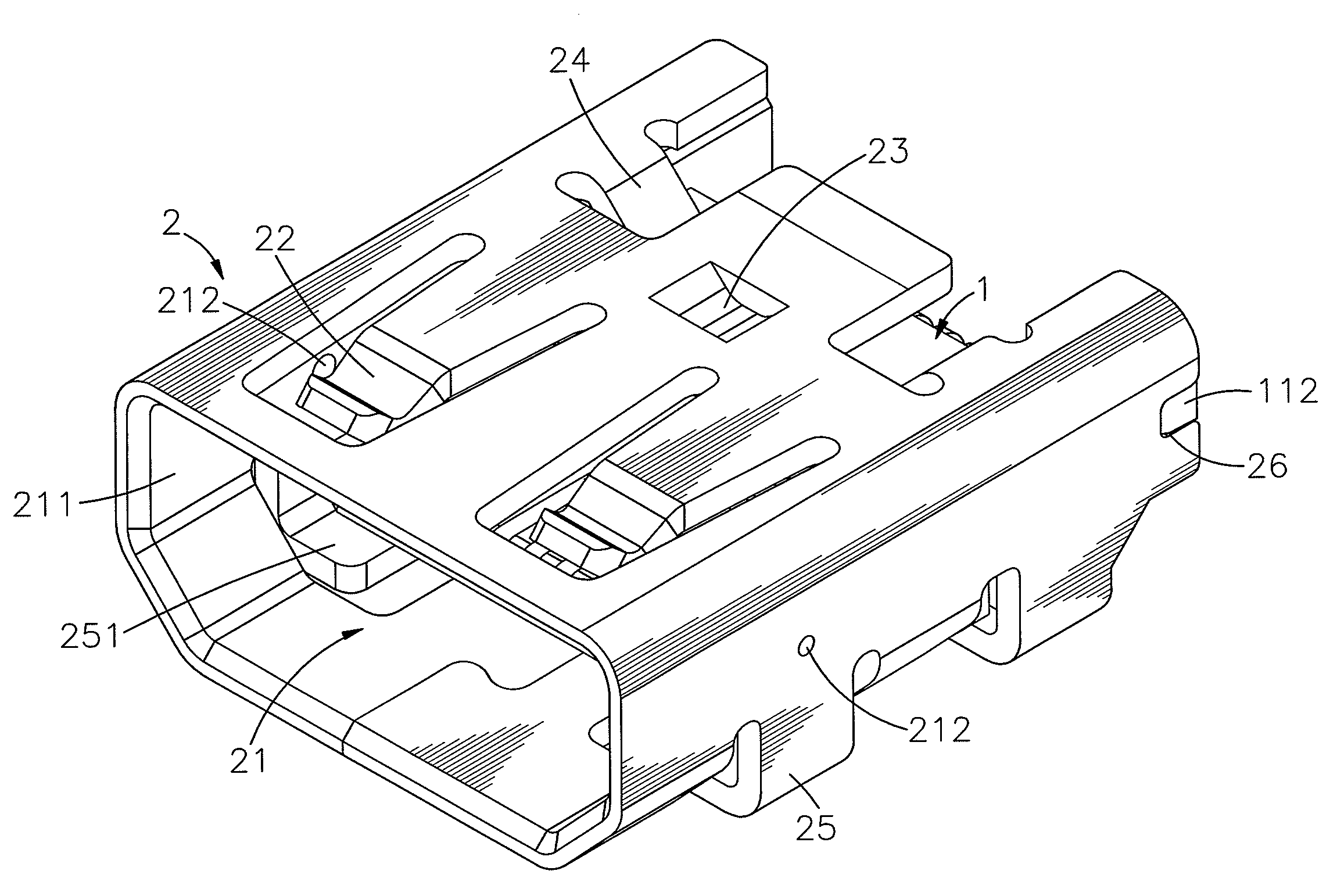
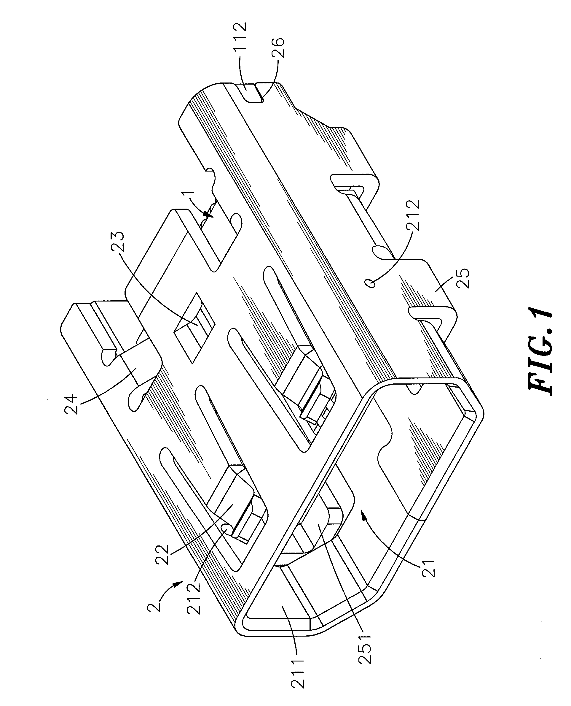
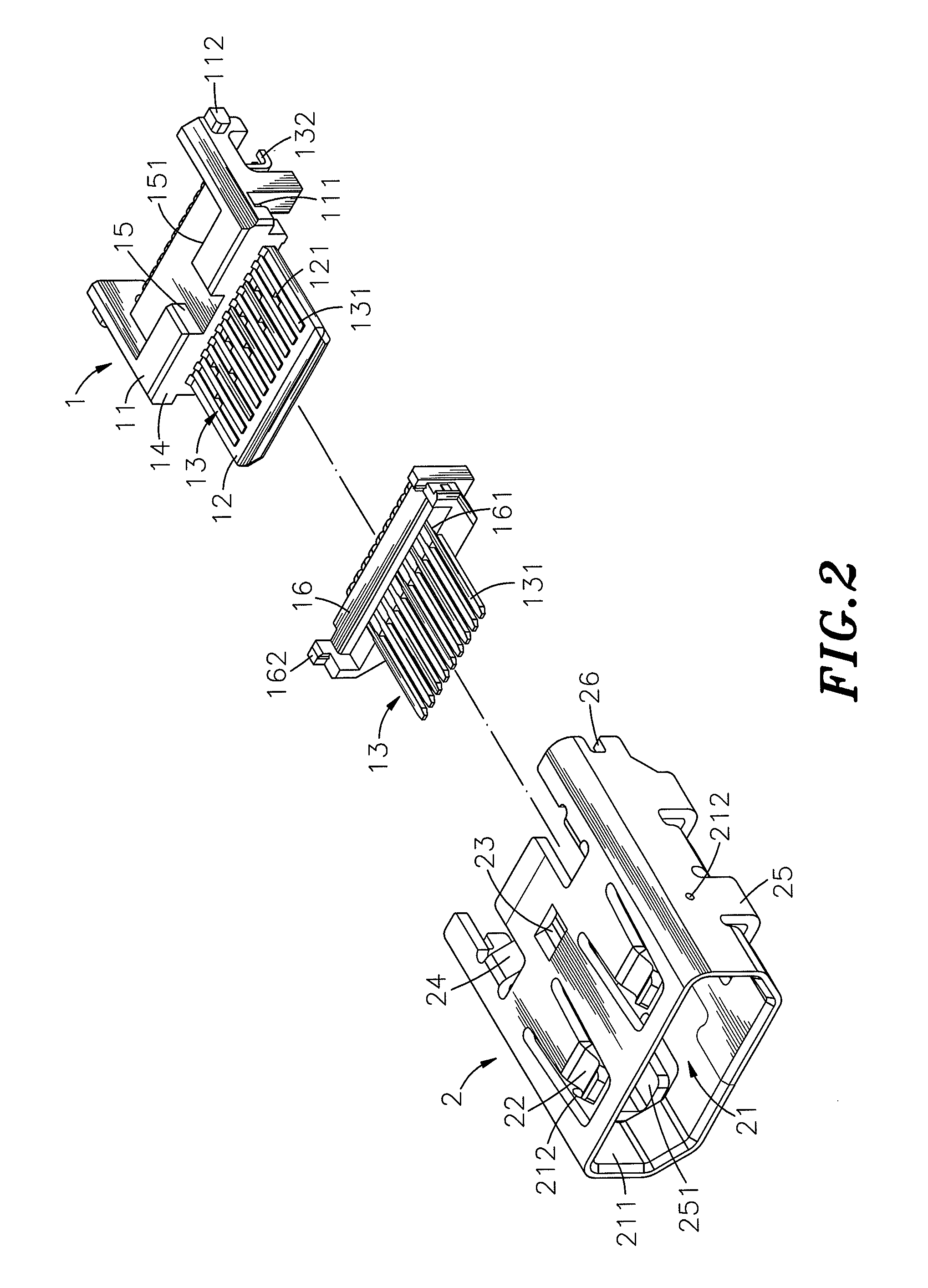
[0022]Referring to FIGS. 1˜4, an electrical connector in accordance with the present invention is shown comprising a connector body 1 and a metal shielding shell 2.

[0023]The connector body 1 comprises an electrically insulative base block 11, an electrically insulative front extension portion 12 forwardly extended from the front side of the electrically insulative base block 11 for insertion into an external electrical connector 3 that is inserted into the electrical connector of the present invention (see FIG. 7), a plurality of terminal grooves 121 arranged on the top and bottom sides of the electrically insulative front extension portion 12, and a plurality of conducting terminals 13 mounted in the electrically insulative base block 11 and respectively positioned in the terminal grooves 121 at the top and bottom sides of the electrically insulative front extension portion 12. The conducting terminals 13 each have a front contact portion 131 suspending outside the associating term...


PUM


Abstract

An electrical connector includes a connector body having an electrically insulative base block with a front vertical stop wall and a locating notch on the middle of front vertical stop wall, an electrically insulative front extension portion forwardly extended from the electrically insulative base block and conducting terminals mounted in the electrically insulative base block and the electrically insulative front extension portion, and a metal shielding shell surrounding the connector body and having a positioning block downwardly protruded from the top wall thereof and engaged into the locating notch of the electrically insulative base block of the connector body to assure connection stability between the connector body and the metal shielding shell and positive contact between the conducting terminals and an inserted external electrical connector.

Description

BACKGROUND OF THE INVENTION[0001]1. Field of the Invention[0002]The present invention relates to electrical connectors and more particularly, to such an electrical connector, which prohibits structural damage or relative movement between the connector body and metal shielding shell thereof upon insertion of an external electrical connector, assuring structural stability and reliability.[0003]2. Description of the Related Art[0004]Following fast development of computer technology, notebook computers are intensively used to substitute for desk computers for the advantages of small size and high mobility. Further, when using a computer to transmit signal or data or connecting a computer to a peripheral apparatus, peripheral interface means is necessary.[0005]To fit small-sized, light-weighted and mobile characteristics of advanced electronic apparatus, USB and Mini USB connectors are created. Mini USB connectors include A-type and B-type to fit different plug specifications. These conn...

Claims


Application Information

Patent Timeline
Patent Type & Authority Patents(United States)
IPC IPC(8): H01R24/00
CPCH01R13/502H01R13/6594H01R24/62H01R12/724H01R2107/00
Inventor CHIU, WEN-TAYEN, MING-HUISHIH, WEN-SHUANSU, YI-HAO
Owner CHANT SINCERE
Why Eureka
Try Eureka