Strengthened equipment cases and methods of making same

a technology of reinforced equipment and equipment cases, applied in the direction of machines/engines, packaged goods, packaging foodstuffs, etc., can solve the problems of container thermal expansion or thermal contraction under lower temperatures, container distortion, and difficulty in stacking properly, so as to reduce or eliminate the distortion of stackable elements, increase the rotation rate, and reduce the effect of distortion

Active Publication Date: 2011-09-13
BECKLIN HLDG
View PDF44 Cites 3 Cited by
  • Summary
  • Abstract
  • Description
  • Claims
  • Application Information

AI Technical Summary

Benefits of technology

A stackable equipment container includes at least one reinforcement panel made of a composite material attached to the container on an interior surface proximate an arrangement of stackable elements. The panel is attached to the container using spin-weld plugs installed at a high rotation rate. Through the installation of the spin-weld plugs, the panel becomes fused or welded to the container. In one embodiment, the rotation rate of the spin-weld plugs during installation is sufficient to cause the panel and container to locally vulcanize with each other and with the spin-weld plugs. The panel provides the container with increased strength and operates to minimize or eliminate distortion of the stackable elements.

Problems solved by technology

However, one drawback of the rotomolded containers made from the LLDPE is these containers may thermally expand under higher temperatures or thermally contract under lower temperatures.
This thermal expansion or contraction results in distortion of the case, especially distortion of the stackable elements, and makes the containers difficult to stack properly.

Method used


Image

  • Strengthened equipment cases and methods of making same
  • Strengthened equipment cases and methods of making same
  • Strengthened equipment cases and methods of making same

Examples


Embodiment Construction

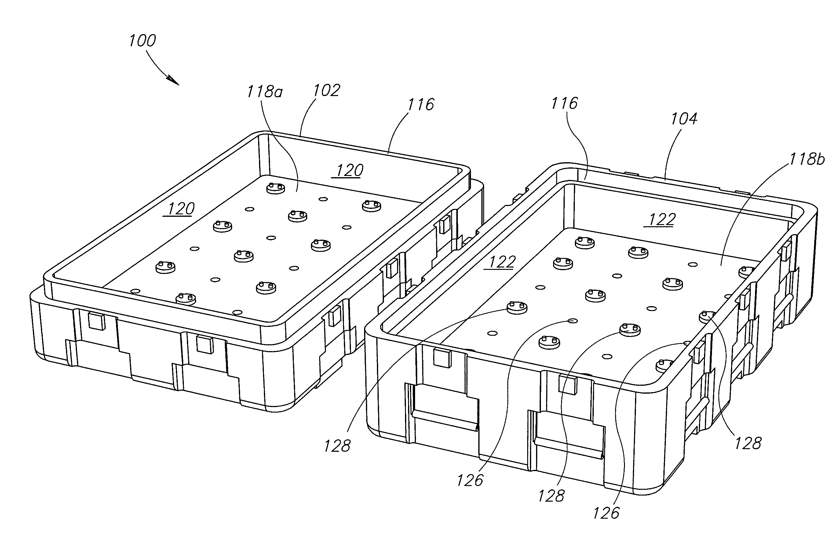
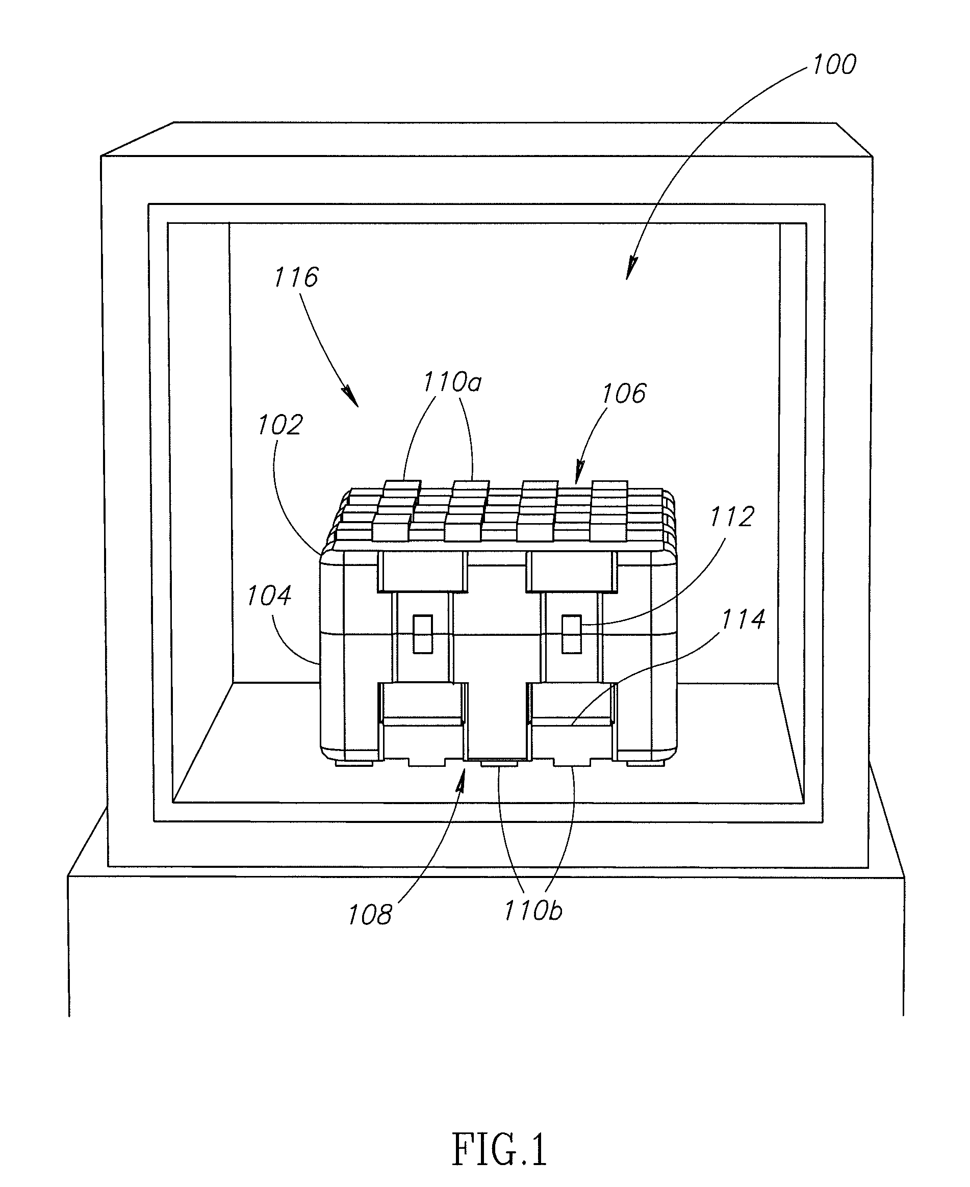
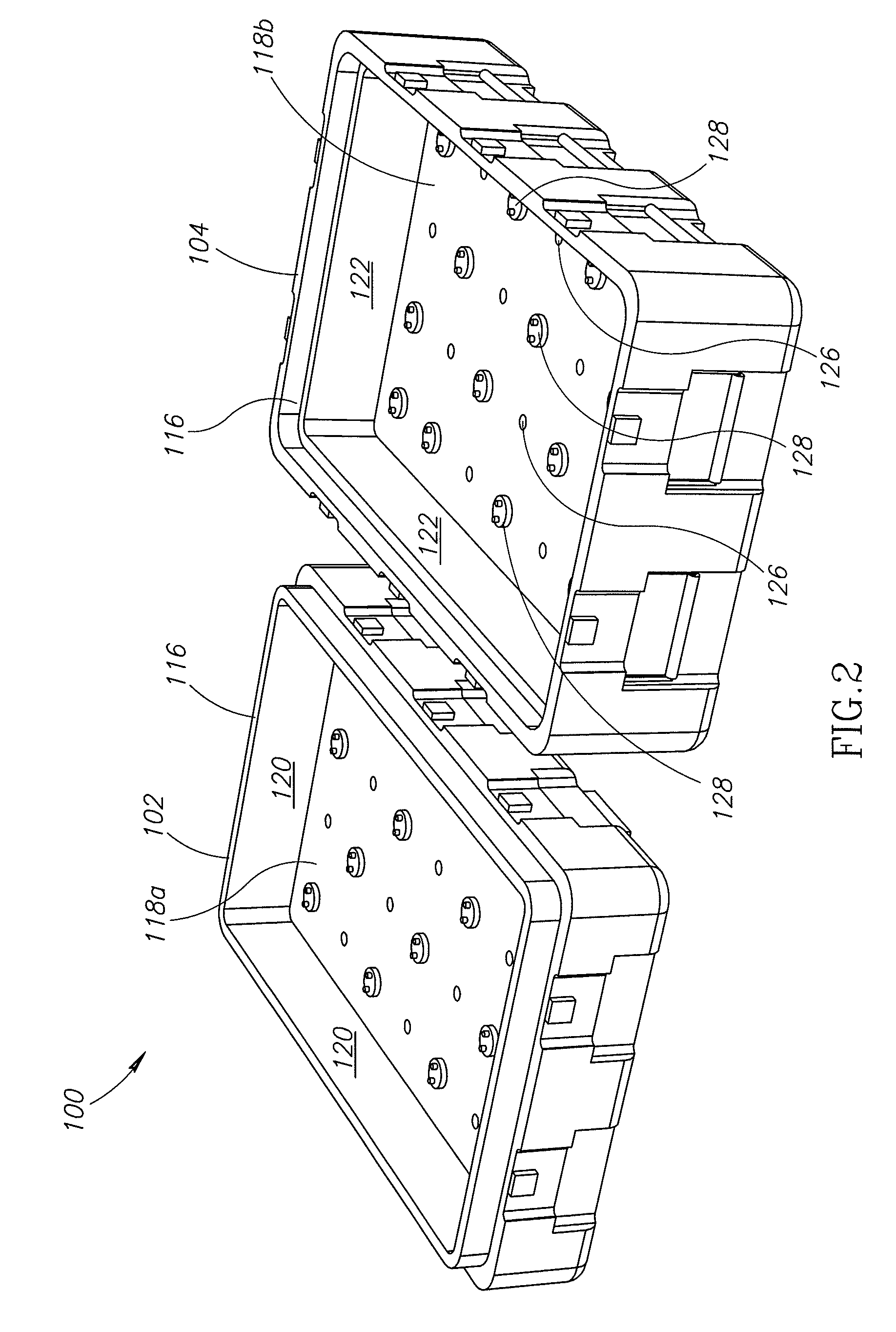
In an example of the present invention, a stackable equipment container includes at least one reinforcement panel made of a composite material. The panel is attached to the container using spin-weld plugs installed at a high rotation rate. Through the installation of the spin-weld plugs, the panel becomes fused or welded to the container. In one embodiment, the rotation rate of the spin-weld plugs during installation is sufficient to cause the panel and container to locally vulcanize with each other and with the spin-weld plugs. The panel provides the container with increased strength and operates to minimize or eliminate distortion of the stackable elements of the container.

In the following description, certain specific details are set forth in order to provide a thorough understanding of various embodiments of the invention. However, one skilled in the art will understand that the invention may be practiced without these details. In other instances, well-known structures associate...


PUM

PropertyMeasurementUnit
rotation rateaaaaaaaaaa
densityaaaaaaaaaa
stiffnessaaaaaaaaaa

Abstract

A stackable equipment container includes at least one reinforcement panel made of a composite material attached to the container on an interior surface proximate an arrangement of stackable elements. The panel is attached to the container using spin-weld plugs installed at a high rotation rate. Through the installation of the spin-weld plugs, the panel becomes fused or welded to the container. In one embodiment, the rotation rate of the spin-weld plugs during installation is sufficient to cause the panel and container to locally vulcanize with each other and with the spin-weld plugs. The panel provides the container with increased strength and operates to minimize or eliminate distortion of the stackable elements.

Description

BACKGROUND OF THE INVENTIONVarious types of containers for moving equipment, such as electronics equipment or other types of delicate devices and systems, been employed in military and commercial environments. Many of these containers include stackable elements arranged so the containers may be stacked one on top of another. The stackable elements operate the keep an upper situated container from laterally sliding off of a lower situated container. In addition, some of these containers are rotomolded using a linier low density polyethylene (LLDPE) material. Because the containers are often used in transit operations, for example on ships, trucks, airplanes and other vehicles, the containers may be subjected to different temperature conditions over their operational life. However, one drawback of the rotomolded containers made from the LLDPE is these containers may thermally expand under higher temperatures or thermally contract under lower temperatures. This thermal expansion or con...

Claims


Application Information

Patent Timeline
Patent Type & Authority Patents(United States)
IPC IPC(8): B32B37/00
CPCB29C65/0672B29C65/606B29C66/304B29C66/721B29C66/939B65D21/0223B65D25/02B29C65/069B29C66/93451B29C65/562Y10T29/49966B29K2023/0625B29K2023/12B29K2105/06B29K2309/08Y10T156/109B29C66/71B29C66/7212B29C66/72141B29C66/73921B29K2023/04B29K2023/10
Inventor BECKLIN, DENNIS M.
Owner BECKLIN HLDG
Why Eureka
Try Eureka