Side entry circuit breaker

a circuit breaker and side entry technology, applied in the direction of snap-action arrangements, protective switch terminals/connections, coupling device connections, etc., can solve problems such as configuration of lugs

Active Publication Date: 2011-09-13
SIEMENS IND INC
View PDF12 Cites 5 Cited by
  • Summary
  • Abstract
  • Description
  • Claims
  • Application Information

AI Technical Summary

Benefits of technology

[0011]Accordingly, it is an object of the invention to configure a circuit breaker that eliminates the need to route cables with U-bends or S-bends and offers the flexibility of either left or right side cable routing, or both in any application, while complying with electrical code over spacing requirements.
[0012]Independent from the first object of the invention, it is an additional and separate object to provide additional cable routing flexibility to enable load cables to be inserted vertically into the circuit breaker lugs in a plane normal to and above the circuit breaker front cover in applications where it is desirable to route cables in a plane above the circuit breaker.
[0013]These and other objects are achieved by the circuit breaker of the present invention that enables selective side feed of load cables from either the left or right side or a combination of both. The circuit breaker of the present invention allows an enclosure designer to minimize wiring spacing within electrical enclosures by avoiding the need for complex cable bends, while complying with electrical code over surface spacing requirements.

Problems solved by technology

As a result of the over surface requirement, a drawback of the prior art breaker design 40 is that the lugs were configured at the factory for only left side load cable access, or in one other variation top access similar to the prior art circuit breaker of FIG. 2.

Method used


Image

  • Side entry circuit breaker
  • Side entry circuit breaker
  • Side entry circuit breaker

Examples


Embodiment Construction

[0037]After considering the following description, those skilled in the art will clearly realize that the teachings of my invention can be readily utilized in making and using the circuit breaker of the present invention.

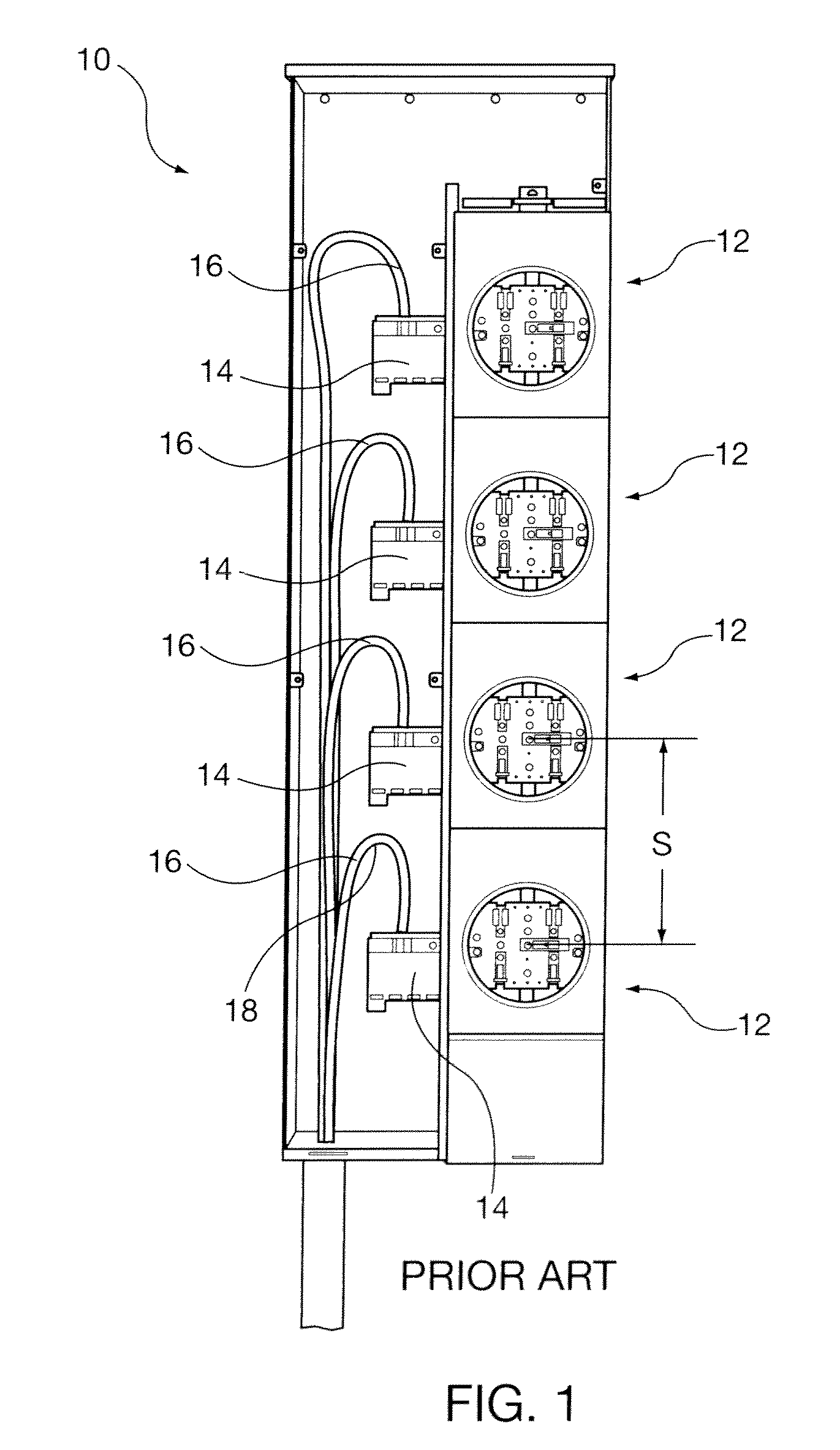
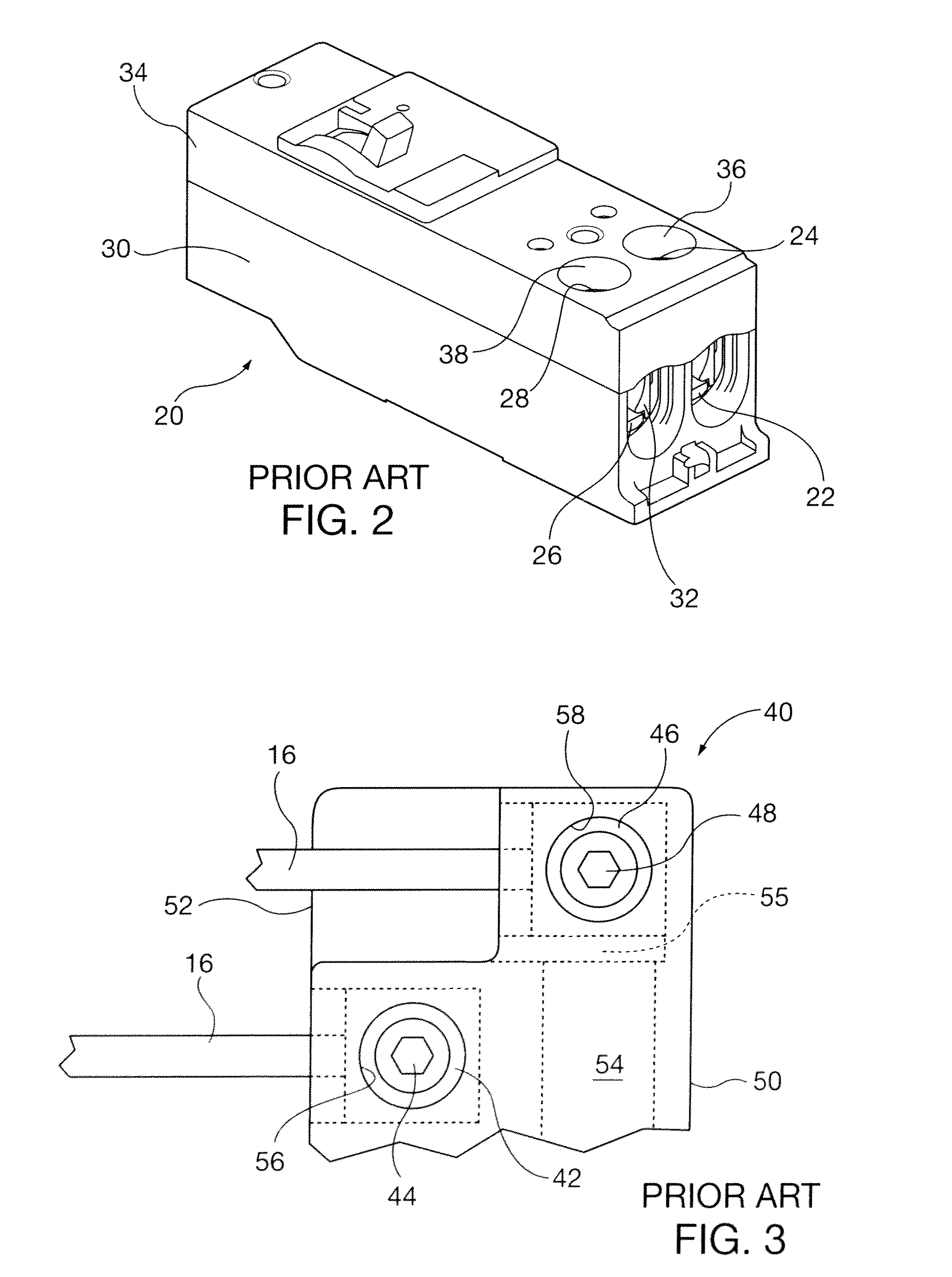
[0038]FIGS. 1-3, depicting prior art electrical enclosures and circuit breaker designs have been described in the Background of the Disclosure section, above. The prior art circuit breakers did not offer the design application flexibility to enable left or right side wiring connection or a combination of both. Lugs were permanently oriented to enable only left or top side wiring, among other reasons to comply with electrical code over surface spacing requirements, so that wire or cable conductors were maintained at a minimum distance from other components within the electrical enclosure.

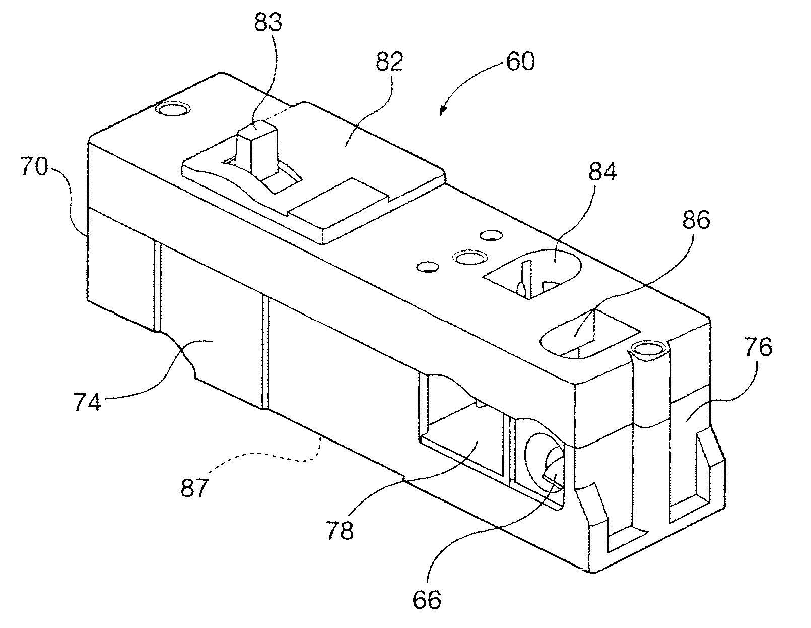
[0039]An embodiment of the circuit breakers of the present invention that enables selective left or right or combination of both side wiring is shown in FIGS. 4-6. Referring generall...


PUM


Abstract

A circuit breaker enables selective left, right or a combination of both side connection to a power conductor, such as a cable or wire. Side connection eliminates the need for large radius U-bends of the power conductor that is normally required when using top connection circuit breakers. An electrically non-conductive cavity commonly defined by left and right sides of the circuit breaker housing receives the power conductor in a connector such as a lug. The circuit breaker may have a visualization window oriented to observe whether excessive cable is projecting out of the lug, so as to confirm compliance with electrical code over surface spacing requirements. In some embodiments, the circuit breaker lugs are vertically oriented above its front cover surface in a receptacle portion of the housing. The receptacle may be constructed for selective lug orientation in horizontal or vertical positions by the installer.

Description

CLAIM TO PRIORITY[0001]This application claims the benefit of United States provisional patent application entitled “SIDE ENTRY CIRCUIT BREAKER” filed Feb. 19, 2008 and assigned Ser. No. 61 / 029,589, and also provisional patent application entitled “CIRCUIT BREAKER WITH DETACHABLE RECEPTACLE” filed Jul. 30, 2008 and assigned Ser. No. 61 / 084,719, both of which are incorporated by reference herein.BACKGROUND OF THE DISCLOSURE[0002]1. Field of the Invention[0003]The present invention is directed to circuit breakers for circuit protection and control of electrical distribution systems. It is suitable for application in low voltage alternating current electrical systems commonly employed in residential and commercial structures.[0004]2. Description of the Prior Art[0005]Circuit breakers are often mounted in electrical enclosures, such as metering stacks. Referring to FIG. 1, the metering enclosure 10 is of an exemplary type commonly used in multiple unit occupancy buildings. The enclosure...

Claims


Application Information

Patent Timeline
Patent Type & Authority Patents(United States)
IPC IPC(8): H01H9/00
CPCH01H71/08H01H71/0228H01H2011/0037
Inventor SIMMONS, ROY
Owner SIEMENS IND INC
Why Eureka
Try Eureka