
Virtual walls in infrared based RTLS systems

a virtual wall and infrared technology, applied in wave based measurement systems, angle measurement, instruments, etc., can solve the problems of insufficient accuracy of rf based methods to support room and sub-room level accuracies, lack of reception, and inability to meet the needs of users,

Active Publication Date: 2011-09-13
CENTRAK
View PDF5 Cites 25 Cited by
  • Summary
  • Abstract
  • Description
  • Claims
  • Application Information

AI Technical Summary

Benefits of technology

[0008]The present invention further relates to a method for locating a portable device in an enclosure having a location defining a virtual wall. The method includes a) transmitting an interfering infrared signal (IIS) from a first infrared (IR) transmitter and a data signal from a second IR transmitter, where the data signal includes a corresponding transmitter location ID and b) setting a signal to noise ratio (SNR) threshold of a portable device based on a level of the transmitted IIS signal that is received by the p...

Problems solved by technology

The RF based methods typically do not provide enough accuracy to support room and sub-room level accuracies, because the RF transmissions may penetrate walls.
This type of RTL system, thus, is occasionally prone to a lack of reception by the receiver base stations when the line of sight is blocked, making it susceptible to reliability problems.

Method used


Image

  • Virtual walls in infrared based RTLS systems
  • Virtual walls in infrared based RTLS systems
  • Virtual walls in infrared based RTLS systems

Examples


Embodiment Construction

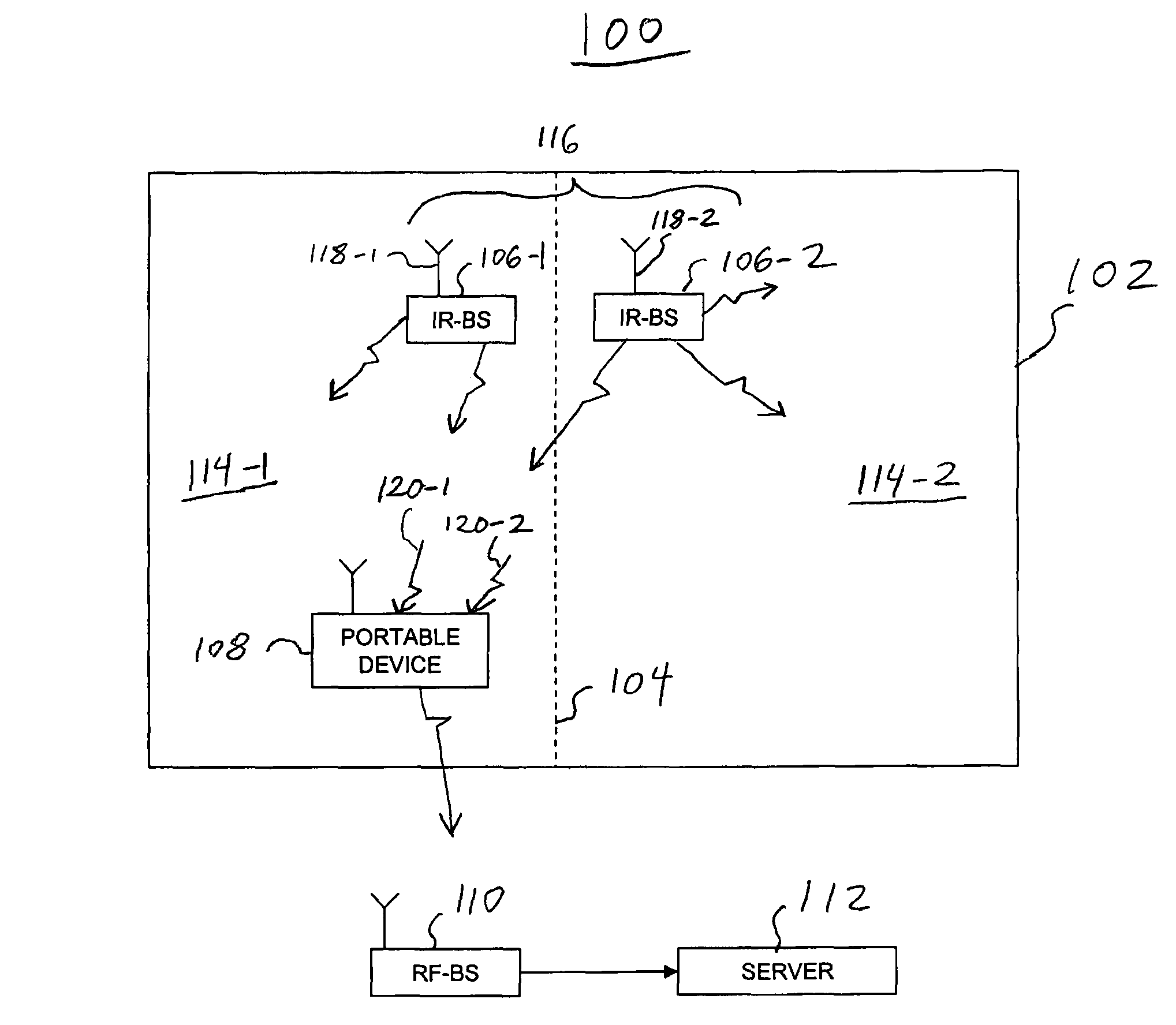
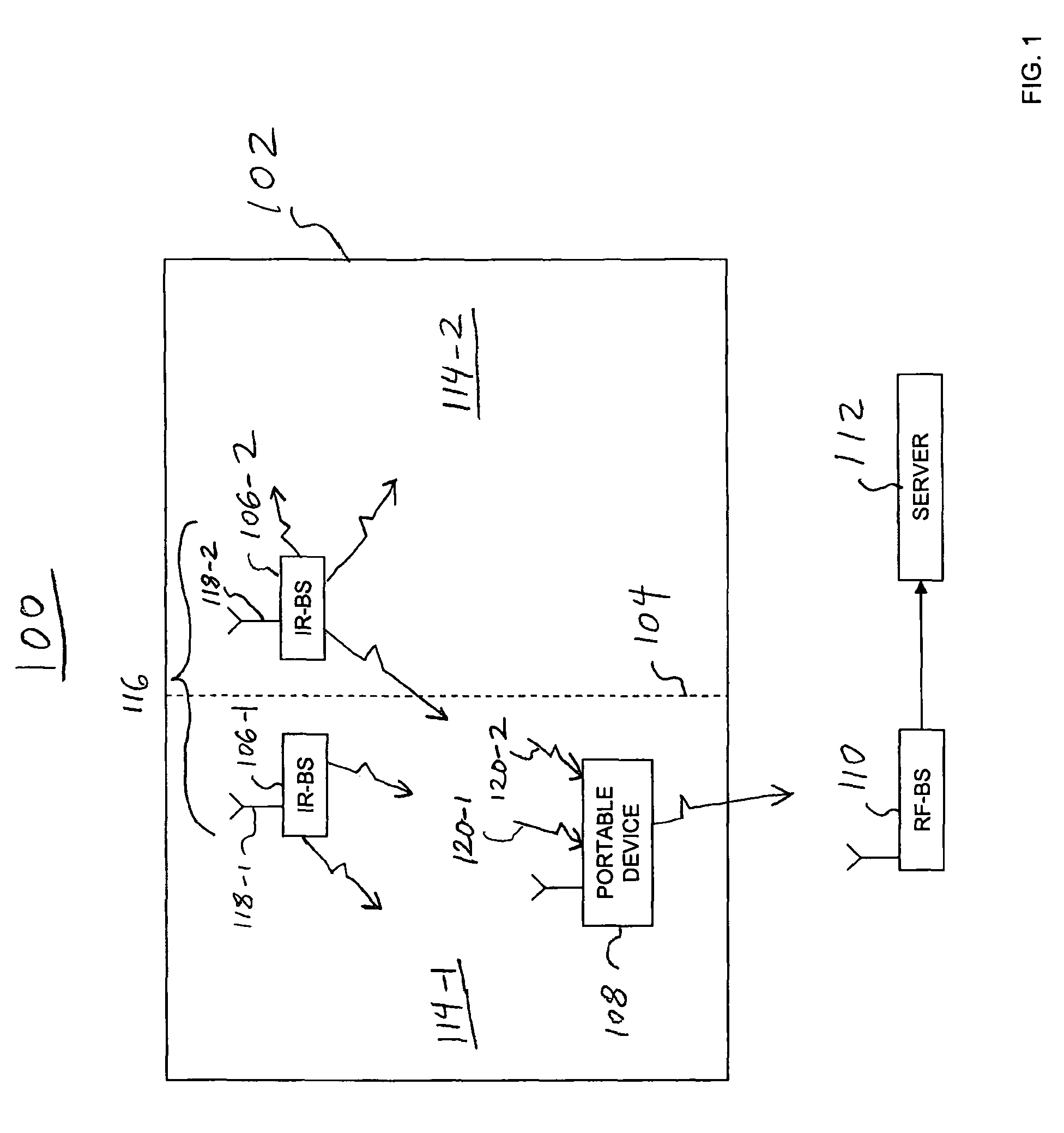
[0020]As described above, there are generally two methods used by infrared RTL systems to determine a physical location of a portable device in an enclosure. In the first method, a mobile portable device transmits an infrared signal to a stationary infrared receiver base station, represented as a DATA signal. In the transmission, the portable device includes its device ID (with possibly other information) as part of the DATA signal. The stationary infrared receiver base station receives the DATA signal from the portable device and communicates (either wired or wirelessly) the received device ID, along with a base station ID to a central station. The central station associates the portable device ID with the known location of the receiver base station to determine the physical location of the portable device.

[0021]In the second method, stationary base-stations (typically one in a room or in isolated zones) transmit infrared DATA signals that include the respective base station ID (an...


PUM


Abstract

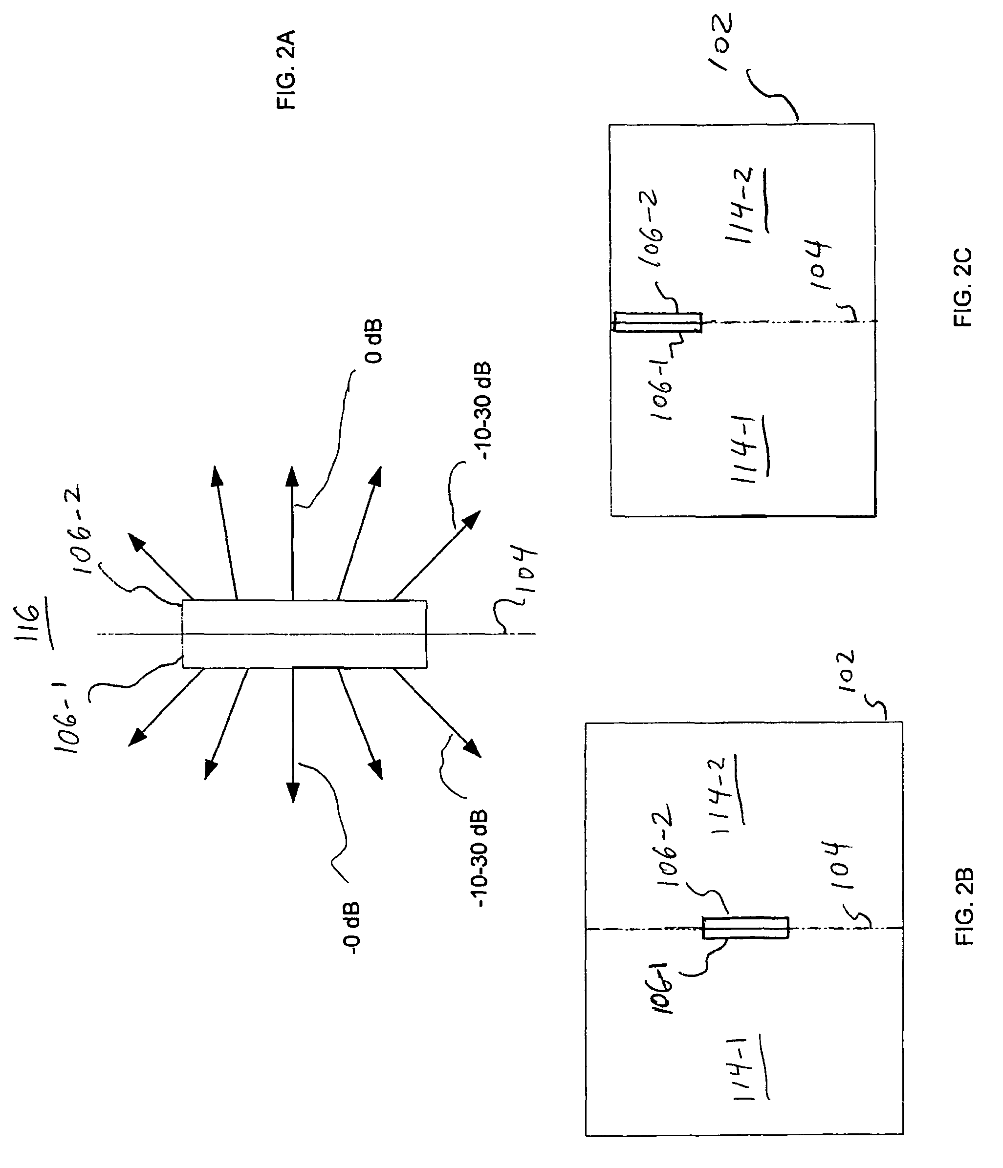
Methods and systems for locating a portable device in an enclosure having a location defining a virtual wall are provided. The system includes first and second infrared (IR) transmitters directed to opposite sides of the virtual wall. Each of the transmitters is configured to selectively transmit an interfering IR signal (IIS) and a data signal including a corresponding transmitter location ID.

Description

CROSS REFERENCE TO RELATED APPLICATIONS[0001]This patent application claims the benefit of priority from U.S. Provisional patent application No. 60 / 959,916, Filed Jul. 17, 2007. The contents of which are incorporated herein by reference.FIELD OF THE INVENTION[0002]The present invention relates to real-time location systems. In particular, the present invention relates to methods and systems for defining virtual walls in an enclosure and for locating portable devices in an enclosure having a location defining a virtual wall.BACKGROUND OF THE INVENTION[0003]Real-time location (RTL) systems have become popular in recent years. Conventional RTL systems typically use radio frequency (RF) transmission to determine location. The RF based methods typically do not provide enough accuracy to support room and sub-room level accuracies, because the RF transmissions may penetrate walls. The use of infrared (IR) has become more popular for some RTL systems in order to support room level accuracy,...

Claims


Application Information

Patent Timeline
IPC IPC(8): G01B11/26
CPCG01S1/70G01S5/16G01S2201/01G01S1/7034
Inventor AMIR, ISRAEL
Owner CENTRAK
Learn More