Blocking element, particularly for a gate used as a checkpoint

a gate and element technology, applied in the field of blocking elements, can solve the problems of large space occupation, large space occupation, and large space occupation of type of blocking units, and achieve the effects of avoiding injury risk, running smoothly, and subject to little wear

Inactive Publication Date: 2011-09-20
MAGNETIC AUTOCONTROL GMBH
View PDF20 Cites 9 Cited by
  • Summary
  • Abstract
  • Description
  • Claims
  • Application Information

AI Technical Summary

Benefits of technology

According to the invention, this is achieved in that the two blocking vanes are mounted close to the floor such that they can pivot about a common pivot axis and their radius corresponds approximately to the height of the support and of the housing, and in that the two blocking vanes can be driven by the drive motor in a manner controlled only by means of a lever system. Driving only by means of a lever system is very functionally reliable and not highly susceptible to faults, and at the same time relatively simple and inexpensive in terms of design and production. Since the blocking vanes are articulated close to the floor and their radius corresponds virtually to the height of the housing, the gate can be covered and blocked over almost its entire height by said blocking vanes.
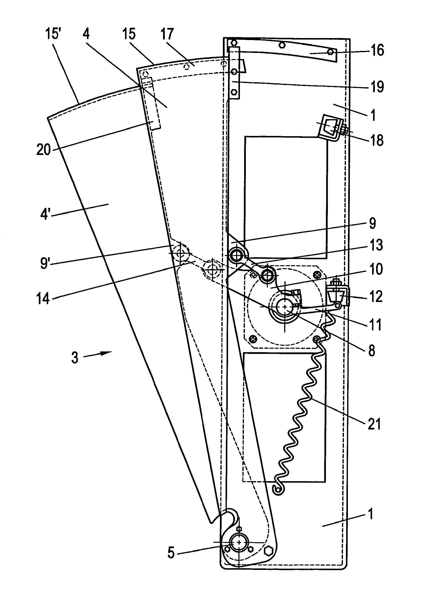
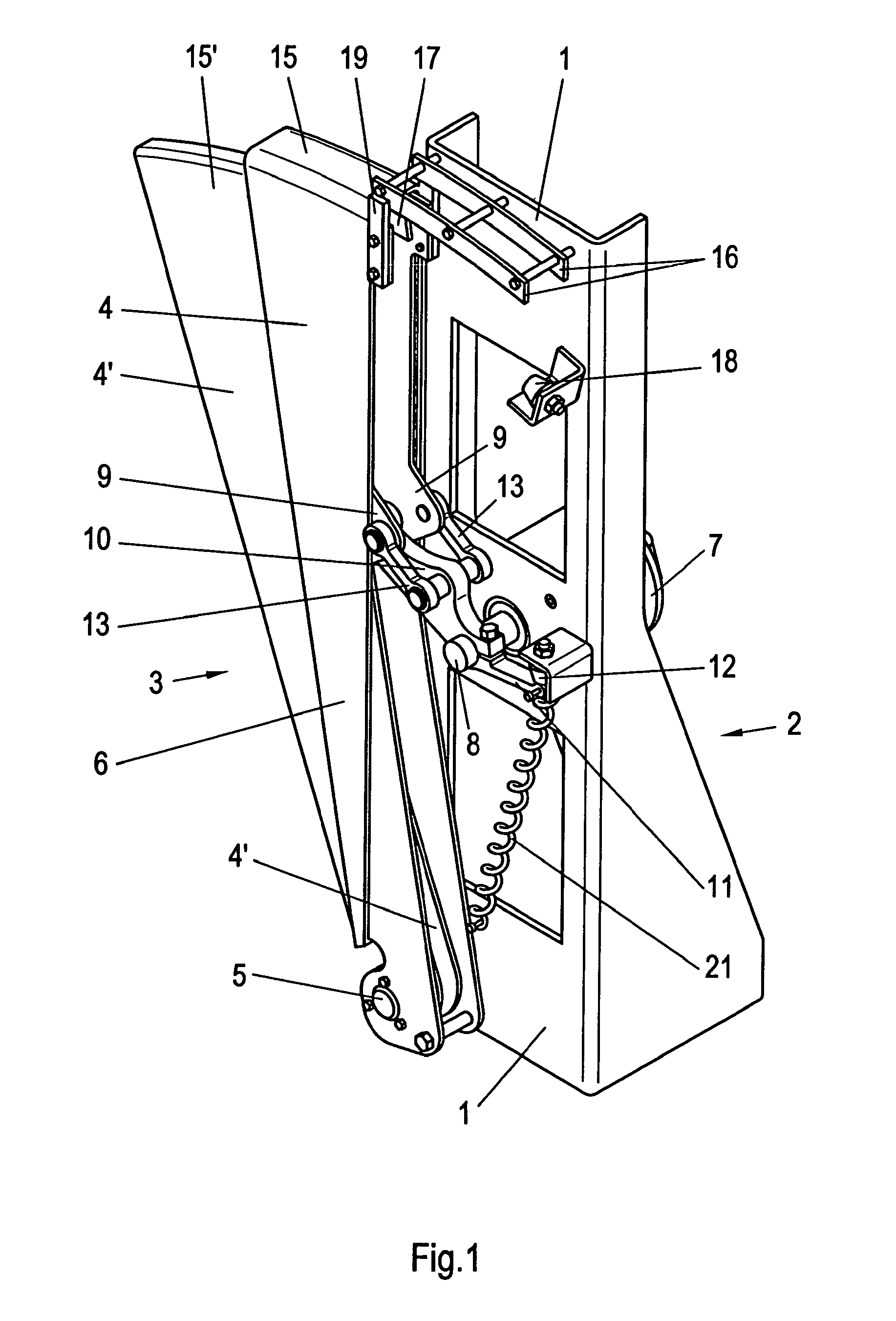
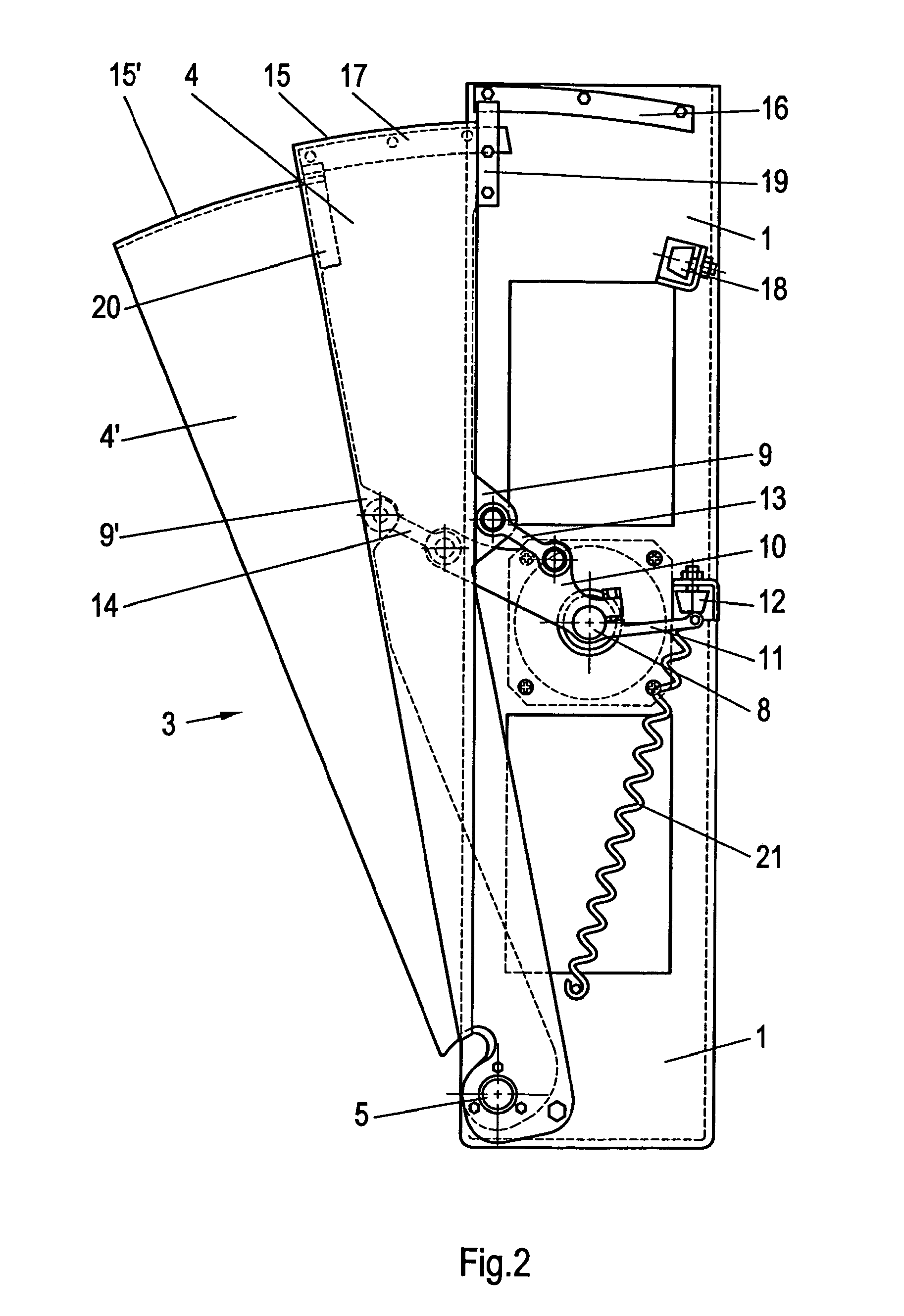
The drive motor and the lever system are preferably arranged approximately halfway up the support and the blocking vanes, and eyes for articulated connection to the transmission levers can be provided on the blocking vanes. As a result, the arrangement is provided with additional stability overall. The drive motor is preferably a brushless DC motor in the form of a direct drive. Short run times of the blocking vanes and low-noise operation can be achieved with this direct drive.
The blocking vanes can be guided on guide rails at their outer faces, which are in the form of an arc of a circle, during their pivoting movement. The guide rails provide the arrangement with additional stability, so that it is possible to form the blocking vanes such that they can cover and block the gate over virtually its entire height and therefore preclude the gate being bypassed from below.
Guide strips, which project beyond the outer wall of the outer blocking vane, are preferably provided on the side walls of said outer blocking vane, by means of which guide strips the outer blocking vane can slide along guide rails, which are formed in the manner of an arc of a circle and are arranged on the support, and accordingly a guide strip which projects beyond the outer wall of the inner blocking vane is provided on the inner blocking vane which can be drawn into the outer blocking vane, by means of which guide strip said inner blocking vane can slide along a guide rail which is formed in the manner of an arc of a circle and is arranged on the inner face of the outer wall of the outer blocking vane. As a result, there is a spacing between the outer faces of the blocking vanes and the guide rails, and contact between the outer faces and the guide rails is thus precluded, so that no friction, no frictional noise, no abrasive wear and no traces of abrasive wear can be produced.
In a further, advantageous refinement, a guide rail, which is formed in the manner of an arc of a circle, is fixed to the support and has on its outer and / or inner curved surface a groove. On the outer blocking vane, a roller or a ball bearing is arranged, between the vane outer wall and the support, on a shaft and engages in the groove in the guide rail; a further guide rail, which is in the form of an arc of a circle, is arranged on the circle-sector-like inner side of the outer blocking vane and likewise has a groove in which a roller or a ball bearing engages, which roller or ball bearing is arranged in the rear, upper region of the inner blocking vane. The outer blocking vane is laterally guided and supported by means of this type of guide too. Abrasive wear and traces of abrasive wear on the blocking vane are avoided.
The blocking vanes are preferably of sandwich construction. They may comprise a very lightweight, but stable, foam insert or honeycomb structure which is coated or provided by adhesive bonding on both sides with a thin and lightweight metal plate or plastic plate, it being possible for the entire unit to be further covered with a soft PUR foam. This contributes to lightweight construction which, as already mentioned, permits very short run times of the blocking vanes of approximately 0.2 seconds. The PUR foam covering protects the inner part of the blocking vanes and contributes to personal protection on account of its softness.

Problems solved by technology

It has been found in various turnstiles of this type that, on account of the comparatively fast rotation which said turnstiles must execute, a high impact force is produced and there is therefore a risk of injury, primarily to children who, on account of their small body size, may be struck in the upper region of the body or even the head by the following rotating blocking arm.
In addition, this type of blocking unit takes up a relatively large amount of space.
The impact force in the respective end position of the barrier also constitutes a problem in barriers of this type, all the more so when quick release and, subsequently, similarly quick renewed blocking of the path is required; in this case, it is necessary to provide measures for damping movement at the end of each pivoting movement, in order to prevent damage.
In addition, a correspondingly large amount of space is likewise required on account of the pivoting movement of the barrier bar through 90°.
In the process, the blocking vanes are subjected to continuous abrasive wear in these guide grooves and traces of this abrasive wear can already be seen from the outside after an extremely short period of operation.
The gear mechanism is very complicated and therefore relatively expensive, and at the same time susceptible to faults and not functionally reliable.
It is subject to continuous abrasive wear and produces disturbing noise, particularly when, for cost reasons, a relatively crude tooth system is selected.

Method used


Image

  • Blocking element, particularly for a gate used as a checkpoint
  • Blocking element, particularly for a gate used as a checkpoint
  • Blocking element, particularly for a gate used as a checkpoint

Examples


Embodiment Construction

.

The blocking element 3 is mounted on the support wall 1 of an elongate, vertical support 2 which has a cross-section which is bent in the form of a U and is installed in a housing (not illustrated) of a pedestrian gate and whose height corresponds virtually to that of this housing. Said blocking element comprises two blocking vanes 4, 4′ in the form of circle sectors which can slide one over the other or one into the other in a fan-like or telescopic manner in order to open the passage (see FIG. 3) and are moved apart in a reverse manner in order to block the passage (FIGS. 1 and 2). On their tapering sector inner side, the blocking vanes 4, 4′ are mounted close to the floor of the housing on the support wall 1 such that they can pivot about a common pivot axis 5. The two blocking vanes 4, 4′ are of sandwich construction. A very lightweight, but nevertheless stable, foam insert, for example comprising metal foam or foam made of another suitable material, or a honeycomb structure ma...


PUM


Abstract

A blocking element for a gate used as a checkpoint includes a housing having a height, a support having a second height and arranged in the housing, a horizontally directed pivot axis furnished on the support, and a pair of blocking vanes each of which are in a form of a circle sector, wherein the pair of blocking vanes are mounted, by way of a tapering sector inner side of the blocking vanes and such that the blocking vanes can pivot about the horizontally directed pivot axis. A drive motor is connected to the blocking vanes on the pivot axis, wherein the drive motor in response to a signal, slides one of the blocking vanes into the other in a telescopic manner from a position which blocks a passage of the gate into a position, which opens the passage of the gate, and wherein the blocking vanes can be drawn apart from one another in order to again block the passage of the gate.

Description

(a) TITLE OF THE INVENTION(b) CROSS-REFERENCE TO RELATED APPLICATIONS.(not applicable)(c) STATEMENT REGARDING FEDERALLY SPONSORED RESEARCH OR DEVELOPMENT.(not applicable)(d) THE NAMES OF THE PARTIES TO A JOINT RESEARCH AGREEMENT.(not applicable)(e) INCORPORATION-BY-REFERENCE OF MATERIAL SUBMITTED ON A COMPACT DISC.(not applicable)(f) BACKGROUND OF THE INVENTION.(1) Field of the Invention.The invention relates to a blocking element, particularly for a gate used as a checkpoint, which comprises two circle-sector-like blocking vanes which are mounted, by way of their narrow sector inner side and such that they can pivot about a horizontally directed pivot axis, on a support which is arranged in the housing and in response to a signal, in a manner driven by a drive motor, can slide one over the other or one into the other in a fan-like or telescopic manner from a position which blocks the passage, in order to open the passage, and can be drawn apart from one another in order to again bl...

Claims


Application Information

Patent Timeline
Patent Type & Authority Patents(United States)
IPC IPC(8): E06B3/94
CPCE06B11/085G07C9/02G07C9/10
Inventor BURGIN, THOMAS
Owner MAGNETIC AUTOCONTROL GMBH
Why Eureka
Try Eureka