Catalytic combustor and method thereof

a combustor and catalyst technology, applied in the direction of combustion process, combustion ignition, lighting and heating apparatus, etc., can solve the problems of fuel evaporation, risk of thermal degradation of catalysts, and few, if any, commercial applications

Active Publication Date: 2011-09-20
ZEMISSION
View PDF8 Cites 4 Cited by
  • Summary
  • Abstract
  • Description
  • Claims
  • Application Information

AI Technical Summary

Problems solved by technology

Typical disadvantages are the requirements of complete fuel evaporation and homogenous air / fuel mixture to eliminate the risk for thermal degradation of the catalyst.
However, when it comes to catalytic combustion of liquid fuels there are still few, if any, commercial applications due to the problem to achieve complete and efficient evaporation of hydrocarbon fuels without accumulation of heavy hydrocarbon residues.
The problem with evaporation of liquid fuels lies in the fact that the evaporator temperature must be controllable depending on the operating conditions of the burner and accumulation of heavy hydrocarbon residuals must be prevented in order to avoid coking.

Method used


Image

  • Catalytic combustor and method thereof
  • Catalytic combustor and method thereof

Examples


Embodiment Construction

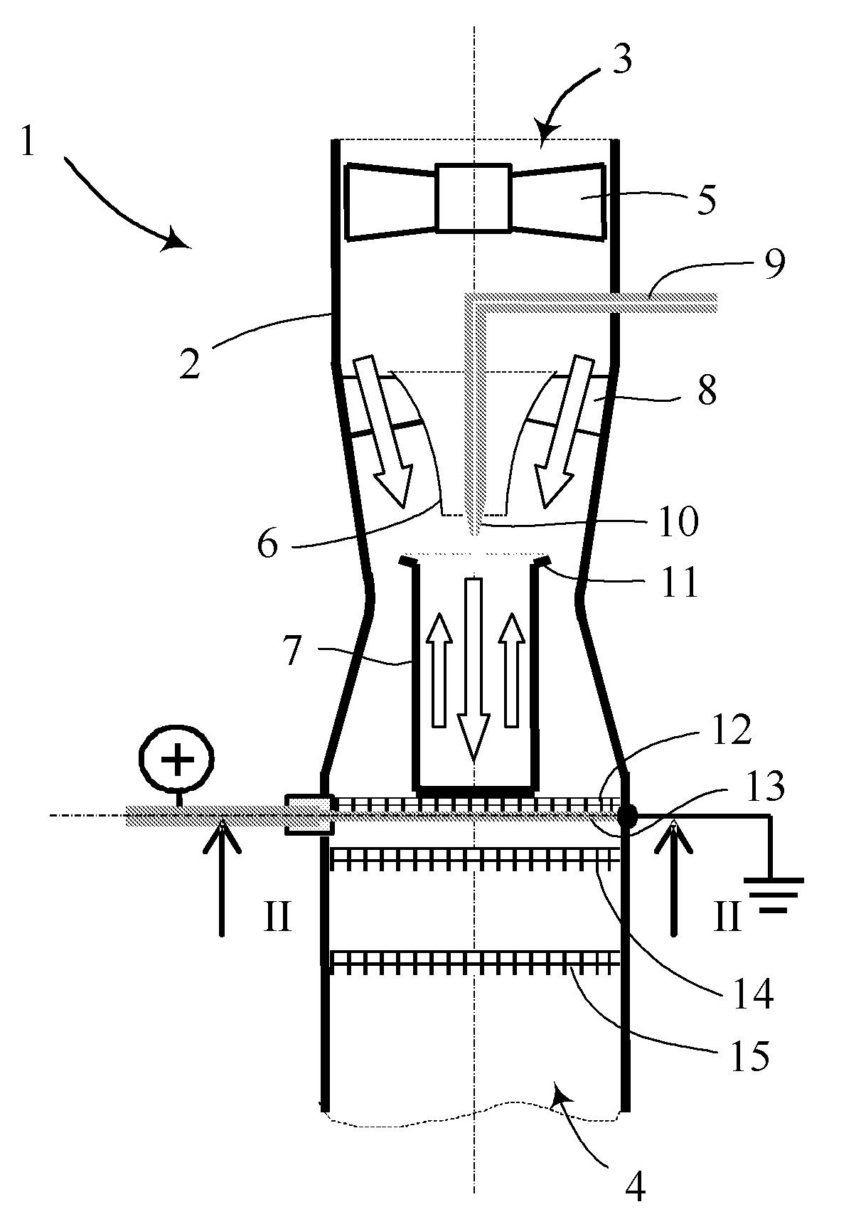
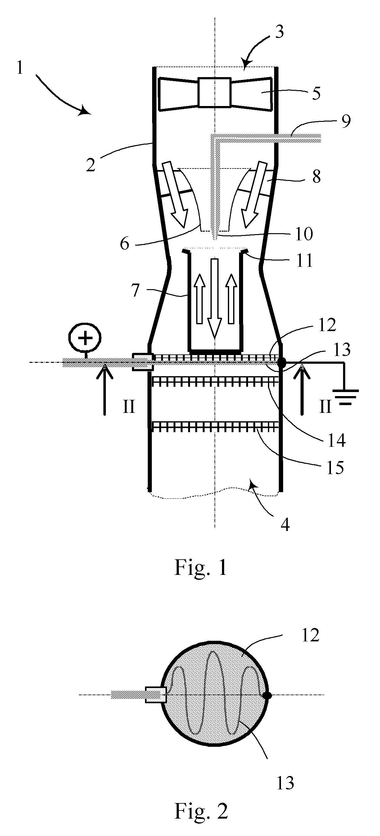
[0008]A catalytic combustor 1 is shown in section in FIG. 1. The combustor comprises a generally cylindrical outer housing 2, forming a venturi in the mid-section, and the housing has an inlet 3 at one end and an outlet 4 at the other end. A fan 5 is provided at the inlet 3, for supplying the combustor 1 with air, and the air is partly directed into a gradually contracted channel 6, leading to a fuel-evaporating device 7. Another part of the airflow is led outside the channel 6, where the air passes swirl vanes 8, located at an inlet to the venturi. A fuel supply pipe 9 enters the housing upstream of the channel 6, and the pipe is provided with a nozzle 10, which can be a simple orifice, for injecting liquid fuel from just below or inside the channel 6 and into the fuel-evaporating device 7. The nozzle 10 is located in the middle of the airflow running through the channel 6. The fuel-evaporating device 7 is equipped with an outwardly extending edge 11 at its upper perimeter, where t...


PUM


Abstract

A catalytic combustor (1) is provided for combustion of gaseous and liquid fuels, which combustor comprises a housing (2) having an inlet (3) and an outlet (4) through which an airflow is directed, and a fuel injector (10) for injecting fuel in the airflow. The combustor also comprises at least one catalytic element (12, 14, 15) for combusting the mixture of air and fuel. A fuel-evaporating device (7) is arranged for evaporating a liquid fuel, which device is heated by the catalytic element (12), either through combustion therein or by means of an electrical heating element (13) arranged adjacent thereto.

Description

FIELD OF THE INVENTION[0001]The present invention relates to a catalytic combustor and more specifically to such a combustor for gaseous and liquid fuels. The invention also relates to a method for starting and operating said catalytic combustor.BACKGROUND OF THE INVENTION[0002]Catalytic combustion in general has many advantages compared to conventional gas phase combustion. The most obvious advantages are the very low emissions, high safety (normally no flame is present and the gas mixture is too lean for gas phase ignition), controllability, wide power range and silent operation. Typical disadvantages are the requirements of complete fuel evaporation and homogenous air / fuel mixture to eliminate the risk for thermal degradation of the catalyst. Due to the fuel evaporation requirement, combustion of gaseous fuels presents fewer challenges than liquid fuel combustion and the commercial applications are increasing. However, when it comes to catalytic combustion of liquid fuels there a...

Claims


Application Information

Patent Timeline
Patent Type & Authority Patents(United States)
IPC IPC(8): F23D11/44F23Q7/06F23C13/02F23C13/04F23C9/00F23D3/40F23D14/12
CPCF23C13/00F23C13/02F23D5/126F23D7/00F23C13/04
Inventor VESTIN, ANDERS ERIK
Owner ZEMISSION
Why Eureka
Try Eureka