Semiconductor sensor device and method for manufacturing same
a sensor device and semiconductor technology, applied in the field of semiconductor sensor devices, can solve the problems of high manufacturing cost of ceramic cases, difficult to make them smaller-sized but also lighter, and high thickness of the cas
- Summary
- Abstract
- Description
- Claims
- Application Information
AI Technical Summary
Benefits of technology
Problems solved by technology
Method used
Image
Examples
example 1
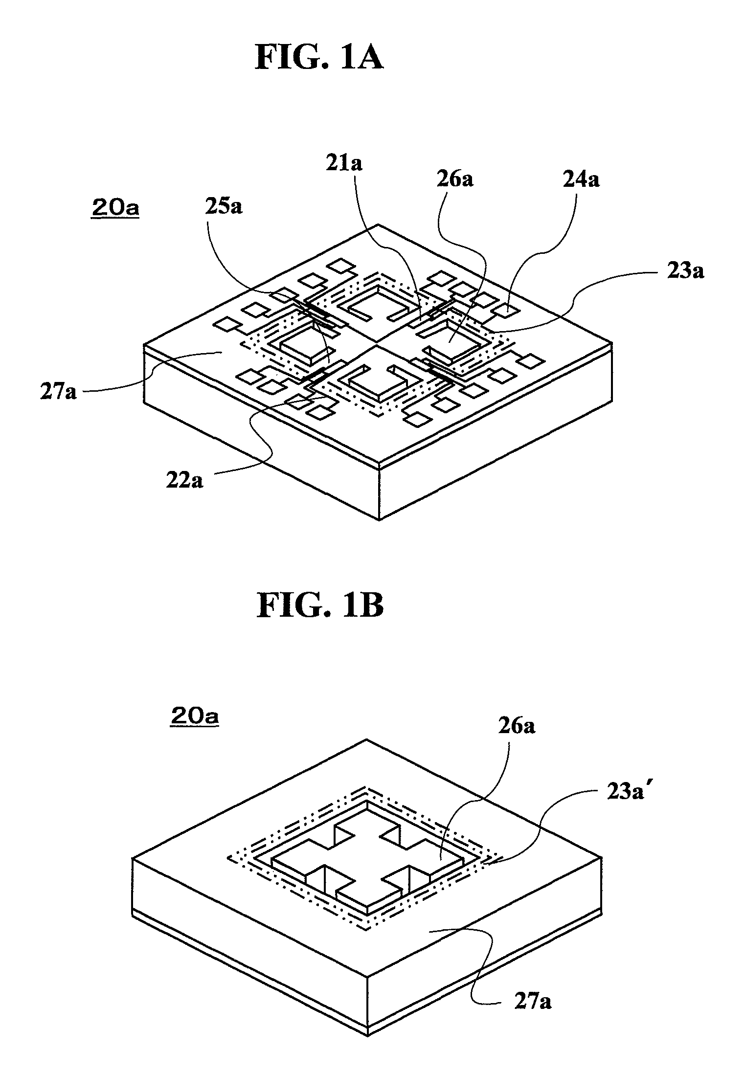
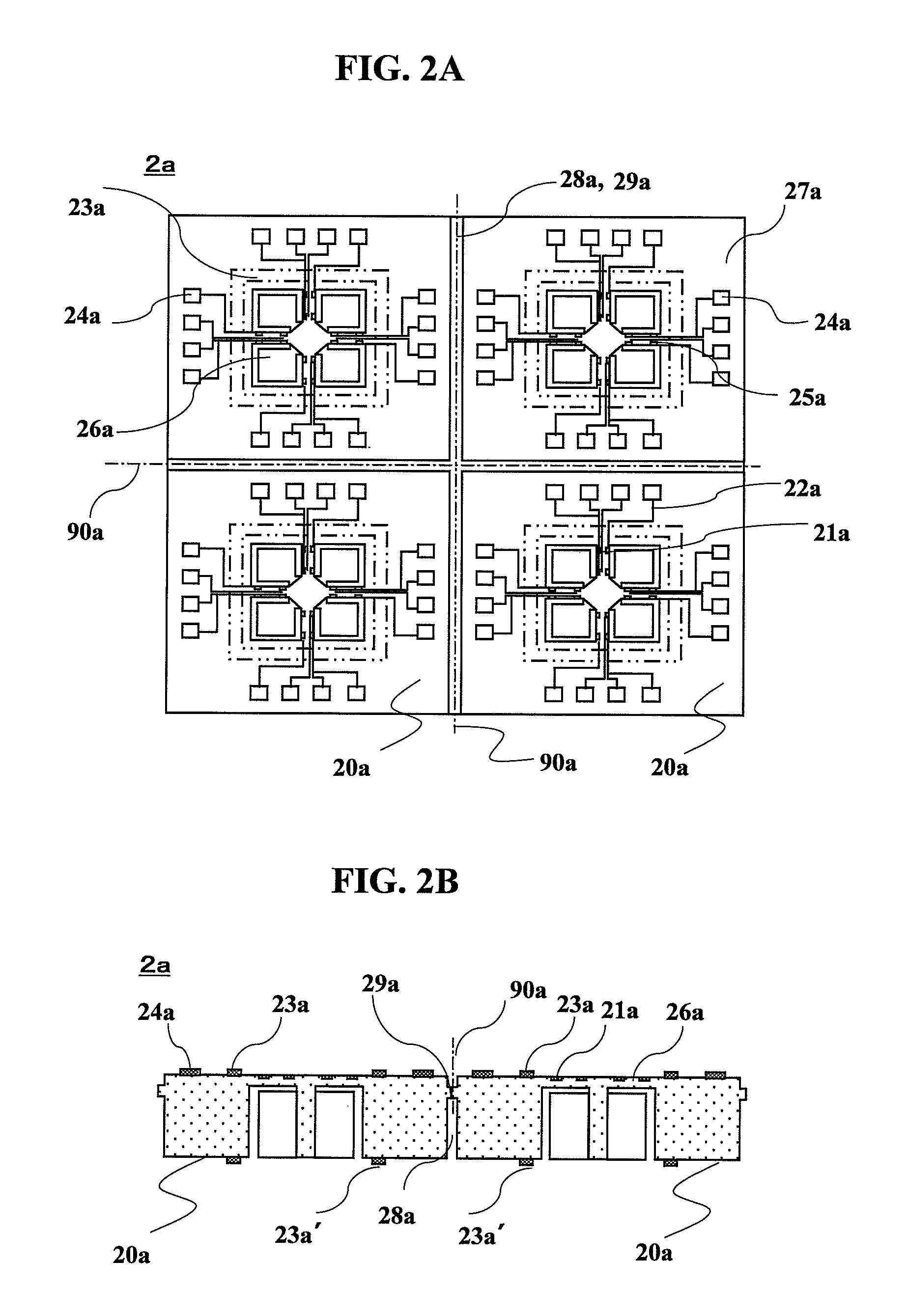
[0080]According to EXAMPLE 1 of the present invention, with reference to FIGS. 1 to 4, the structure of a semiconductor sensor device and a manufacturing process will be now described with an acceleration sensor device as an example. In the following description, a semiconductor sensor substrate and a semiconductor sensor chip manufactured by an MEMS technology are treated as synonymous with an acceleration sensor substrate and an acceleration sensor chip, respectively. FIGS. 1A and 1B are perspective views of a semiconductor sensor chip viewed from the top and the bottom, respectively; FIGS. 2A and 2B are a plan view and a cross-sectional view of the semiconductor sensor substrate, respectively; FIGS. 3A and 3B are a plan view and a cross-sectional view of the cap substrate, respectively; and FIGS. 4A to 4G are explanatory views of a manufacturing process of the semiconductor sensor device.
[0081]As shown in FIGS. 1A and 1B, a semiconductor sensor chip (acceleration sensor chip) 20a...
example 2
[0091]With reference to FIGS. 5 and 6, a semiconductor sensor device (acceleration sensor device) in EXAMPLE 2 of the present invention will be described. FIG. 5 partially illustrates the semiconductor sensor substrate (acceleration sensor substrate) 2b. FIG. 5A is a plan view of the semiconductor sensor substrate 2b on the side having piezo-resistors 21b; and FIG. 5B is a cross-sectional view of FIG. 5A. FIGS. 6A to 6G are explanatory views of a manufacturing process of the semiconductor sensor device 10b of EXAMPLE 2. The semiconductor sensor substrate 2b in FIG. 5 has the same structure and components as the semiconductor sensor substrate of EXAMPLE 1 except for the lack of dividing gutters 28a and couplings 29a, which are provided in the semiconductor sensor substrate of EXAMPLE 1, and therefore its detailed description will be omitted. The shape and material of cap substrates 3b, 3b′ were also the same as those of the cap substrate 3a in EXAMPLE 1.
[0092]The manufacturing proces...
example 3
[0094]Cap chips of EXAMPLE 3 having a crystal orientation different from the cap chips of EXAMPLES 1 and 2 were thinned and divided by wet-etching, while a semiconductor sensor substrate was cut by a cutting wheel to obtain semiconductor sensor chips. With reference to FIG. 7, a description will be made about a manufacturing process of the semiconductor sensor device (acceleration sensor device) of EXAMPLE 3. FIG. 7A is a plan view of a cap substrate 3c or 3c′ viewed from the side to be bonded to a semiconductor sensor substrate (acceleration sensor substrate) 2c; and FIG. 7B is a cross-sectional view of FIG. 7A. Each side surface of the cap substrates 3c, 3c′ was composed of a {100} silicon crystal plane. Drive suppression grooves 31c facing weights of the semiconductor sensor substrate are octagons each surrounded by {100} planes and {111} planes and having edge portions 311c rounded off by over-etching, namely obtuse edges. Outside edge portions 312c corresponding with the edge p...
PUM
 Abstract
Description
Claims
Application Information
 - R&D
- Intellectual Property
- Life Sciences
- Materials
- Tech Scout
- Unparalleled Data Quality
- Higher Quality Content
- 60% Fewer Hallucinations
Browse by: Latest US Patents, China's latest patents, Technical Efficacy Thesaurus, Application Domain, Technology Topic, Popular Technical Reports.
© 2025 PatSnap. All rights reserved.Legal|Privacy policy|Modern Slavery Act Transparency Statement|Sitemap|About US| Contact US: help@patsnap.com


