TM mode evanescent waveguide filter

a waveguide filter and evanescent technology, applied in waveguides, waveguide types, basic electric elements, etc., can solve the problems of less stable or reliable filters without any apparent advantages, and achieve the effects of low cost, high q, and simple manufacturing

Active Publication Date: 2011-09-20
HOWARD JOHN
View PDF10 Cites 13 Cited by
  • Summary
  • Abstract
  • Description
  • Claims
  • Application Information

AI Technical Summary

Benefits of technology

[0009]The present invention relates to waveguide filters utilizing the TM modes in an evanescent waveguide. The Q of such filters surpasses any evanescent, dual and triple mode filters in propagating or evanescent waveguides. The waveguide filter in accordance with the present invention features a small size, as well as ease and simplicity in its manufacture when compared with the above-mentioned conventional filters.
[0010]Filters of exceptionally high Q and very low loss, when compared to all other filters in existence today, can be obtained by employing TM modes in an evanescent waveguide. The TM mode evanescent filter has a higher Q than either the evanescent TE mode standard filter of a single mode propagating waveguide (TM or TE) or even the dual or triple mode filters in evanescent or propagating waveguides.

Problems solved by technology

The electric field modes, or TM modes, are usually avoided since designs using TM modes become more cumbersome and the filters become less stable or reliable without any apparent advantage.

Method used


Image

  • TM mode evanescent waveguide filter
  • TM mode evanescent waveguide filter
  • TM mode evanescent waveguide filter

Examples


Embodiment Construction

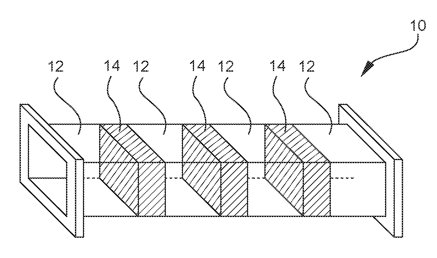
[0027]A waveguide filter 10 formed in accordance with the present invention is shown in FIG. 1. The waveguide filter 10 includes at least one evanescent waveguide section 12 and at least one propagating dielectric filled waveguide section 14 coupled to the at least one evanescent waveguide section. The waveguide filter utilizes at least one TM mode.

[0028]In conventional waveguide filters, the dominant H10 mode is usually present. The electric field modes, or TM modes, are usually avoided since designs using TM modes become more cumbersome and the filters become less stable or reliable without any apparent advantage. However, in below cutoff waveguides, utilization of the electric (E) field advantageously introduces very high Q's in very small and thus lightweight filters.

[0029]The present invention relates to waveguide filters utilizing the TM modes in an evanescent waveguide. The Q of such filters surpasses any evanescent, dual and triple mode filters in propagating or evanescent w...


PUM


Abstract

Waveguide filters utilizing the TM modes in an evanescent waveguide are provided. The Q of such filters surpasses any evanescent, dual and triple mode filters in propagating or evanescent waveguides. The waveguide filter in accordance with the present invention features a small size, as well as ease and simplicity in its manufacture when compared with conventional filters. Filters of exceptionally high Q and very low loss, when compared to conventional filters, can be obtained by employing TM modes in an evanescent waveguide. The TM mode evanescent filter has a higher Q than either the evanescent TE mode standard filter of a single mode propagating waveguide (TM or TE) or even the dual or triple mode filters in evanescent or propagating waveguides.

Description

CROSS-REFERENCE TO RELATED APPLICATION[0001]This application claims priority based on U.S. Provisional Application Ser. No. 60 / 967,168 filed on Aug. 31, 2007, which is incorporated herein by reference in its entirety.BACKGROUND OF THE INVENTION[0002]1. Field of the Invention[0003]The present invention generally relates to waveguide filters, and more particularly to utilizing electric (E) field or TM modes in evanescent waveguides.[0004]2. Brief Discussion of the Related Art[0005]Radio transmitters and receivers require filters to remove or suppress unwanted frequencies from being transmitting or received. The transmitter portion of a radio may generate frequencies that will interfere with the radio system, or that may be prohibited by a radio frequency spectrum governing body. The receiver may need to suppress unwanted signals at different frequencies generated by the transmitter, or received from an external source, which would adversely affect the performance of the receiver.[0006...

Claims


Application Information

Patent Timeline
Patent Type & Authority Patents(United States)
IPC IPC(8): H01P1/208
CPCH01P1/207
Inventor HOWARD, JOHN
Owner HOWARD JOHN
Why Eureka
Try Eureka