System and method for re-aligning antennas

a technology of system and method, applied in the direction of antennas, antenna details, electrical equipment, etc., can solve the problems of dish antennas used for point-to-point network communication to become misaligned, loss of power, and difficulty in maintaining alignment, so as to reduce the cost and delay of antenna misalignment and improve the reliability of network links

Active Publication Date: 2011-09-20
CENTURYLINK INTPROP
View PDF4 Cites 230 Cited by
  • Summary
  • Abstract
  • Description
  • Claims
  • Application Information

AI Technical Summary

Benefits of technology

[0008]To overcome the problems associated with antennas used for point-to-point communications, the principles of the present invention provide for auto re-alignment or remote re-alignment of antennas. By either the antenna being able to self re-align or an operator being able to remotely re-align the antenna, the cost and delay of an antenna becoming misaligned may be reduced for a network operator. Furthermore, reliability of a network link that uses an antenna that is configured using the principles of the present invention may be improved or otherwise remains high.

Problems solved by technology

While the use of dish antennas for WiFi and other network communications is useful for providing long-distance communications between antennas, dish antennas that have such a small angle can result in problems if a misalignment occurs, especially at long distances.
Misalignment of a dish antenna as small as one-half an inch can cause a dramatic loss of power at a range of 20 miles, for example, due to the antenna pattern not being focused on an antenna to which the dish antenna is in communication.
The use of such large antennas may provide for communications qualities suitable for network communications, but may be problematic for maintaining alignment.
Alignment problems may result from a number of reasons, including, and most often, weather conditions.
Even though the brackets 104a and 104b are configured to lock the antennas 106a and 106b in a fixed position, weather conditions that produce a lot of wind, such as rainstorms and hurricanes, may cause the dish antennas being used for point-to-point network communications to become misaligned such that point-to-point communications degrade.
While storms can be a problem, because an antenna may be located high above the ground, a ground wind speed of 20-30 miles per hour may be a wind speed of 80-100 miles per hour at the antenna.
While these problems are generally associated with dish antennas being mounted on towers, the same or similar problems may exist from non-dish antennas or antennas positioned on other structures, such as buildings, poles, or the ground.
One problem that occurs due to the degradation of communications is that reliability of a network degrades to the point of an outage occurring.
Furthermore, the antenna manufacturer may have to lower reliability reporting of the antenna (e.g., from 0.999 to 0.99), which may cause communications carriers to lower their desire to purchase the antenna.
Another problem that results from misalignment of an antenna is that the cost for re-alignment pole or tower climbers (i.e., technicians who climb communications poles or towers) is expensive.
Furthermore, pole climbers are limited in supply and the time to have one perform the re-alignment may take hours or days.
If a misalignment occurs during a storm with precipitation, pole climbers cannot climb the pole, so the misalignment may not be corrected until the storm passes, which may sometimes take several days.
The costs due to misalignment may further be measured in customer attrition, which, if a misalignment occurs each time the wind blows strongly, can be significant.

Method used


Image

  • System and method for re-aligning antennas
  • System and method for re-aligning antennas
  • System and method for re-aligning antennas

Examples


Embodiment Construction

[0025]The principles of the present invention provide a system and method for re-aligning antennas. The description that follows is directed to one or more embodiments, and should not be construed as limiting in nature. In one embodiment, an auto-sensing algorithm is incorporated into a position controller that is attached to an antenna to automatically adjust the elevation and azimuth positions of the antenna. The principles of the present invention may also include a semi-automatic and manual mode for allowing a remote operator to manually adjust the antenna using signal strength or position information returned from a position controller.

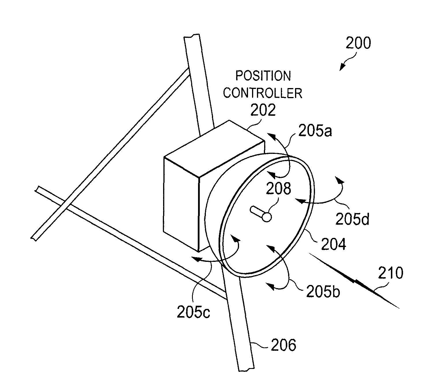
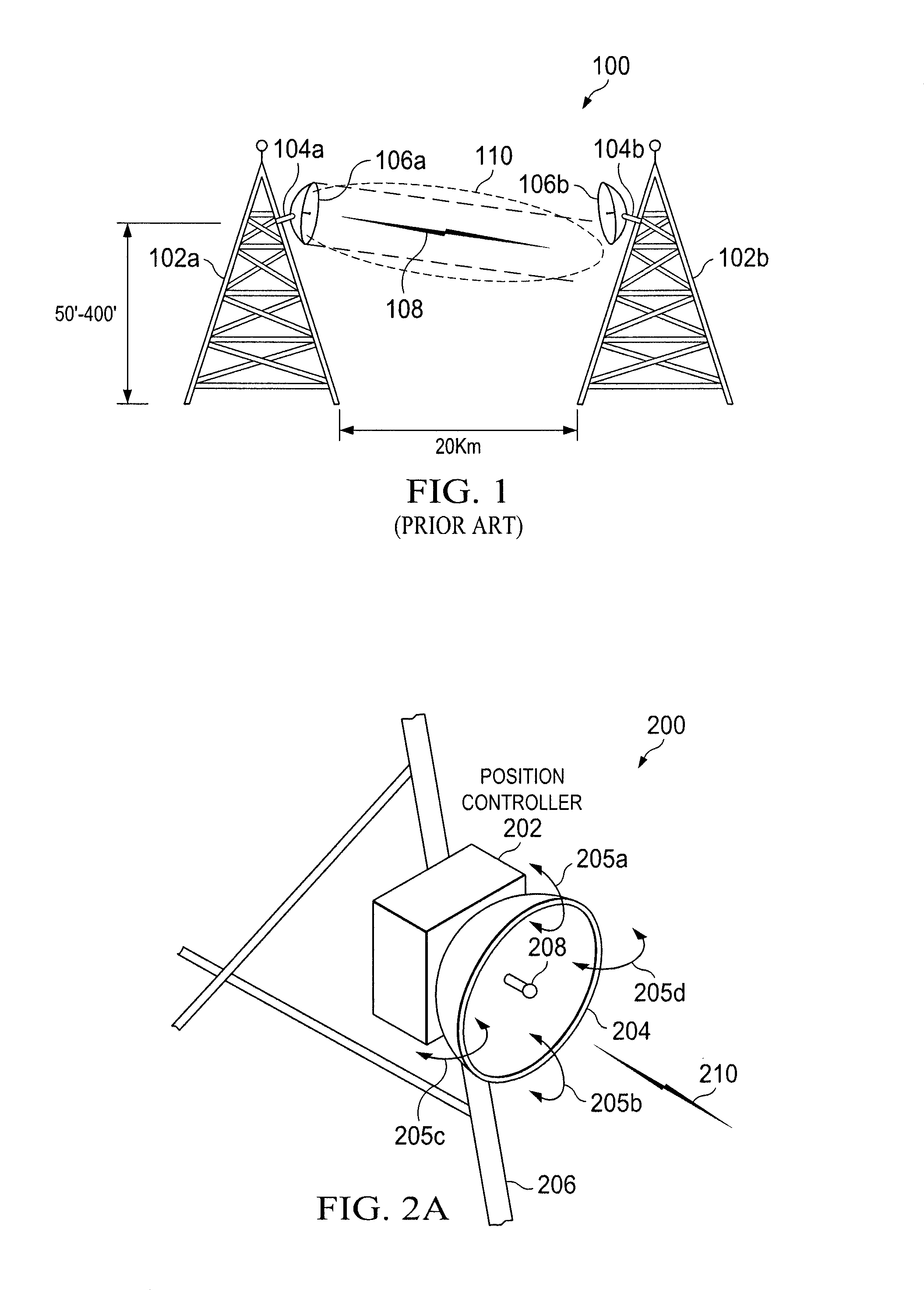
[0026]FIG. 2A is an illustration of an exemplary antenna system 200 including a position controller 202 for re-aligning an antenna. The position controller 202 may be configured to rotate the antenna 106 in both the elevation and azimuth directions as depicted by rotation arrows 205a-205d. In one embodiment, the position controller 202 and antenn...


PUM


Abstract

A system for re-aligning an antenna communicating signals point-to-point. The system may include a first antenna, a second antenna configured to communicate a communications signal with the first antenna using point-to-point communications, and a position controller coupled to the first antenna and configured to re-align the first antenna with respect to the second antenna in response to determining a misalignment of the antenna.

Description

BACKGROUND OF THE INVENTION[0001]Antennas are used for a wide-variety of communications applications. One of the more recent applications for antennas has been for communications of point-to-point links for wireless fidelity “WiFi” communications. Various types of antennas may be used for point-to-point links for WiFi communications, but longer range communications, such as 20 miles, typically use dish-style antennas that have a radiation pattern that focuses an antenna beam more intensely along a communication path with another antenna. For example, while a flat panel antenna may have an antenna beam with a 60 degree angle, a dish antenna may have an antenna beam with a 6 degree angle, a much narrower beam than the flat panel antenna beam.[0002]While the use of dish antennas for WiFi and other network communications is useful for providing long-distance communications between antennas, dish antennas that have such a small angle can result in problems if a misalignment occurs, espec...

Claims


Application Information

Patent Timeline
Patent Type & Authority Patents(United States)
IPC IPC(8): H01Q3/00
CPCH01Q1/125H01Q3/005H01Q3/02
Inventor SMOYER, CLINTON J.SMITH, SHANE M.
Owner CENTURYLINK INTPROP
Why Eureka
Try Eureka