Electrostatic chuck

a technology of electrostatic chuck and chuck body, which is applied in the manufacture of basic electric elements, electrical equipment, semiconductor/solid-state devices, etc., can solve the problems of difficult to predict the lowering of the contact area caused by grinding, complicated manufacturing process of electrostatic chuck, etc., to prevent the leakage of coolant gas, reduce the manufacturing cost of electrostatic chuck, and simplify the manufacturing process. effect of electrostatic chuck

Active Publication Date: 2011-09-20
SHINKO ELECTRIC IND CO LTD
View PDF5 Cites 148 Cited by
  • Summary
  • Abstract
  • Description
  • Claims
  • Application Information

AI Technical Summary

Benefits of technology

[0016]As a result of discussion to solve the problem described above, the inventor et al. found out that only the tip faces of projection parts formed on an attraction and fix face of a dielectric layer are ground, whereby scattering of particles caused by contact with a plate member can be prevented and the contact area of the plate member coming in contact with the tip face of each projection part does not change before and after grinding and that a coolant gas flow path where a coolant gas flows is opened to the tip face of each projection part, whereby heat of the plate member can be removed rapidly, and has reached the invention.
[0028]the tip face of a peripheral wall of the same height as the projection part, formed along the periphery of the dielectric layer is ground to be formed as a flat face, so that the flat face can come in contact with the plate member for preventing leakage of the coolant gas flowing out between the dielectric layer and the attraction member.
[0029]In the electrostatic chuck according to the invention, only the tip faces of the projection parts formed on the attraction and fix face of the dielectric layer are ground. Thus, the contact area of each tip face coming in contact with the plate member can be prevented from being different from the design value because of grinding. Thus, if the valley part between the projection parts is not ground, the tip faces of the projection parts coming in contact with the plate member are ground, so that minute projections of each tip face can be prevented from scattering as particles when coming in contact with the plate member.
[0030]Since grinding performed for the tip faces of the projection parts is easy as compared with grinding of the side face of the projection part, so that the manufacturing process of the electrostatic chuck can be simplified.
[0031]Further, the coolant gas flow path where a coolant gas flows is opened to the tip face of each of the projection parts, so that the heat added to the plate member can be removed rapidly with the coolant gas flowing out from the coolant gas flow path and working can be performed on the plate member with a predetermined attraction force maintained.
[0032]Consequently, according to the electrostatic chuck according to the invention, the manufacturing cost of the electrostatic chuck can be reduced and precise working can be performed on the attracted and fixed plate member.

Problems solved by technology

In the electrostatic chuck shown in FIG. 5, however, the full face of the attraction and fix face containing the projection parts 102 of the dielectric layer 100 is ground and thus the manufacturing process of the electrostatic chuck is complicated.
It is difficult to predict lowering of the contact area caused by grinding.

Method used


Image

  • Electrostatic chuck
  • Electrostatic chuck
  • Electrostatic chuck

Examples


Embodiment Construction

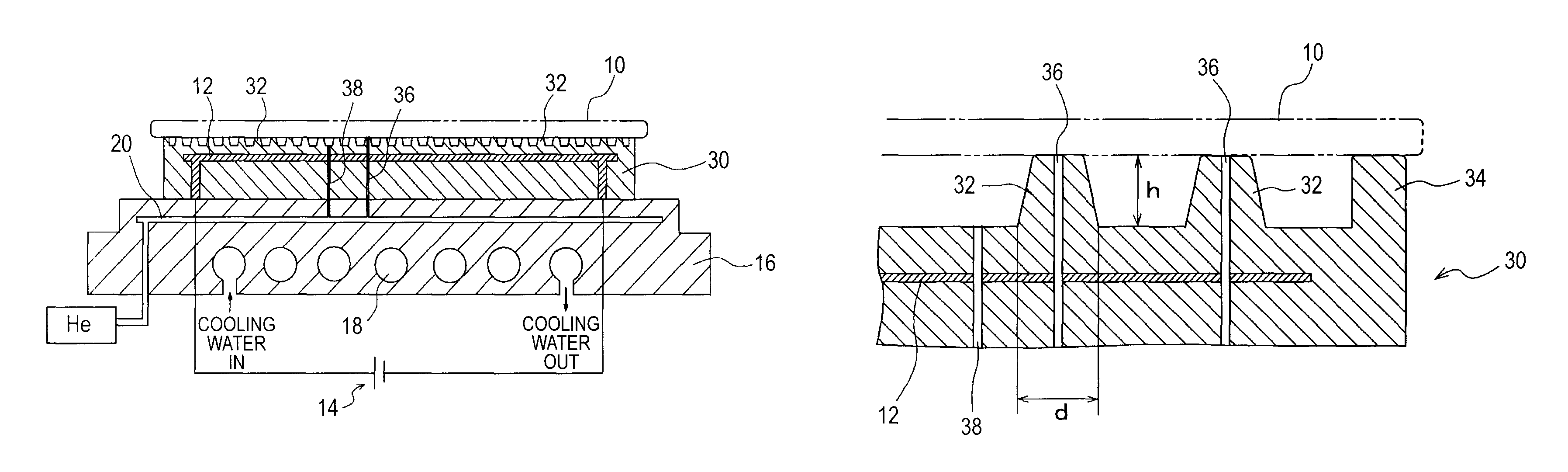
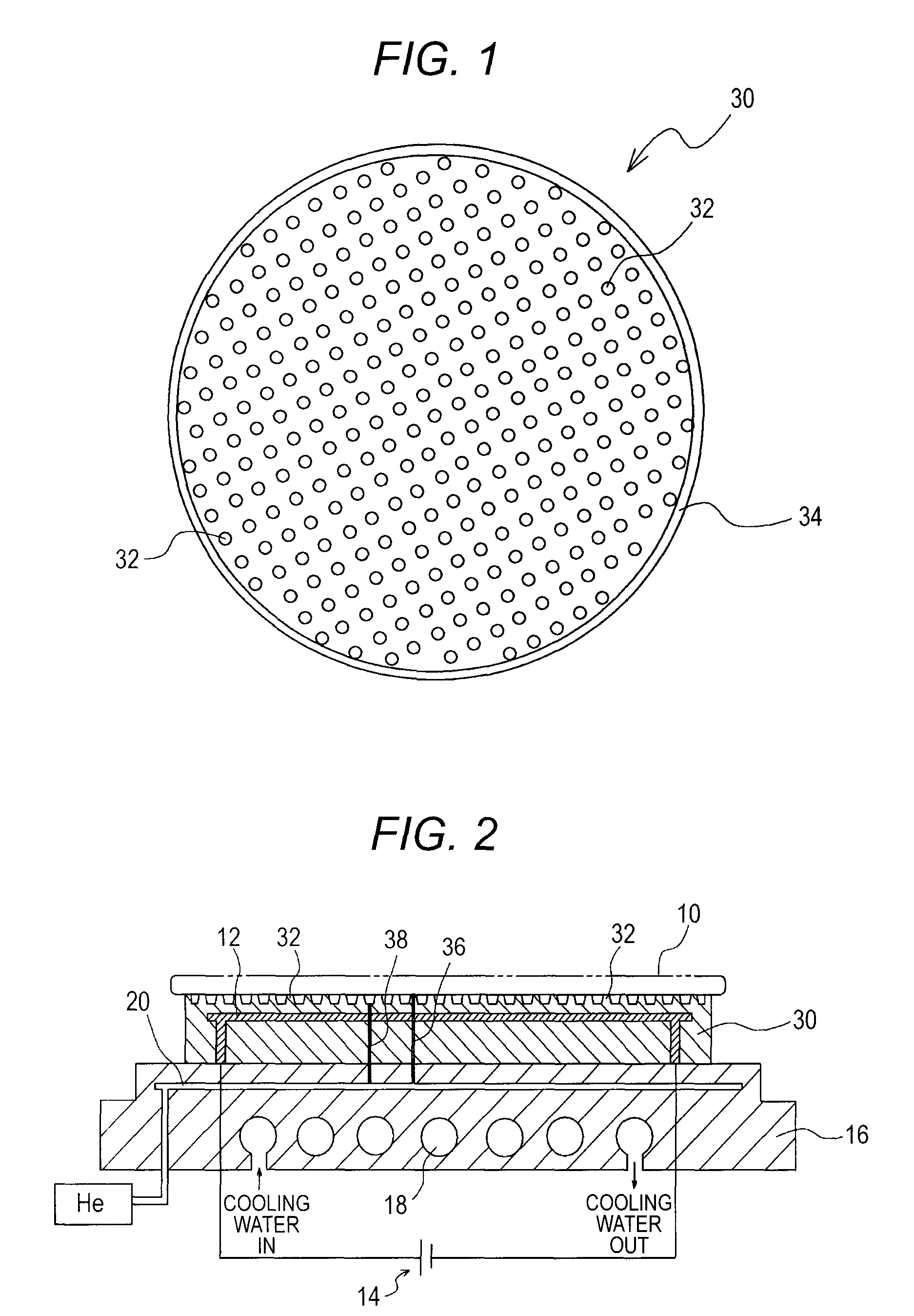
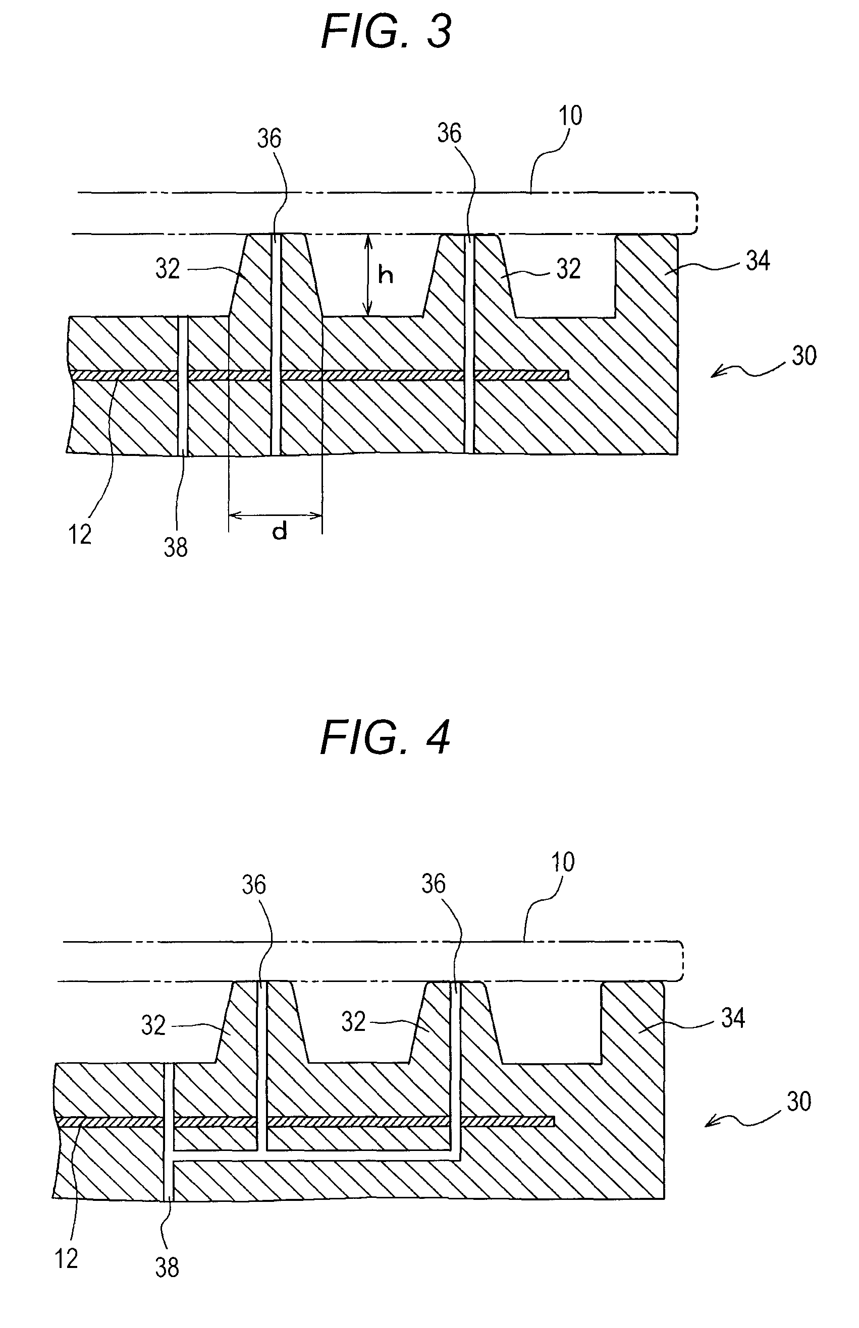
[0039]FIGS. 1 and 2 show an example of an electrostatic chuck according to the invention. A circular dielectric layer 30 to form the electrostatic chuck shown in FIG. 1 is formed of alumina. A large number of projection parts 32, 32, . . . formed on the attraction and fix face of the dielectric layer 30 are surrounded by a peripheral wall 34 with a tip face as a flat face along the periphery of the dielectric layer 30.

[0040]Further, as shown in FIG. 2, an internal electrode 12 connected to a DC power supply 14 is formed in the dielectric layer 30 shown in FIG. 1. The dielectric layer 30 is placed on a base plate 16.

[0041]Formed in the base plate 16 are a cooling water pipe line 18 for introducing cooling water and a coolant gas introduction path 20 into which helium as a coolant gas in a portion near to the dielectric layer 30.

[0042]A coolant gas flow, path 36 opened to the tip face of each of the projection parts 32, 32, . . . formed on the attraction and fix face of the dielectric...


PUM


Abstract

An electrostatic chuck includes a dielectric layer 30 formed with an attraction and fix face onto which a plate member 10 is attracted and fixed, wherein the attraction and fix face of the dielectric layer 30 is formed with a plurality of projection parts 32 each with only a tip face abutting the plate member 10 formed as a flat face by grinding and formed with a coolant gas flow path 36 where a coolant gas flows is opened to the flat face of each of the projection parts 32.

Description

CROSS-REFERENCE TO RELATED APPLICATION[0001]This application is based on and claims priority under 35 U.S.C. §119 from Japanese Patent Application No. 2009-047767 filed on Mar. 2, 2009.BACKGROUND OF THE INVENTION[0002]1. Technical Field[0003]This invention relates to an electrostatic chuck.[0004]2. Related Arts[0005]Patent Document 1 proposes an electrostatic chuck shown in FIG. 5 as an electrostatic chuck for attracting and fixing a plate member of a wafer, etc.[0006]The electrostatic chuck shown in FIG. 5 is formed with a plurality of projection parts 102, 102, . . . each having a flat tip face, formed on an attraction and fix face of a dielectric layer 100, and an exit of a coolant gas flow path 104 is opened in a valley part formed between the projection parts 102 and 102.[0007]Further, in the electrostatic chuck shown in FIG. 5, the full face of the attraction and fix face containing the tip end faces, side faces, and valley part faces of the projection parts 102 is ground.[000...

Claims


Application Information

Patent Timeline
Patent Type & Authority Patents(United States)
IPC IPC(8): H01L21/683H01T23/00
CPCH01L21/6833
Inventor YONEKURA, HIROSHITAMAGAWA, KOKI
Owner SHINKO ELECTRIC IND CO LTD
Why Eureka
Try Eureka