
Wear assembly for excavating machines

a technology for excavating machines and wear parts, which is applied in the direction of mechanical machines/dredgers, soil shifting machines/dredgers, constructions, etc., can solve the problems of decreasing resistance and concomitant stress in the upper leg, and achieves better protection of the lip from wear, less stress, and better support.

Active Publication Date: 2011-09-27
ESCO GRP LLC
View PDF32 Cites 93 Cited by
  • Summary
  • Abstract
  • Description
  • Claims
  • Application Information

AI Technical Summary

Benefits of technology

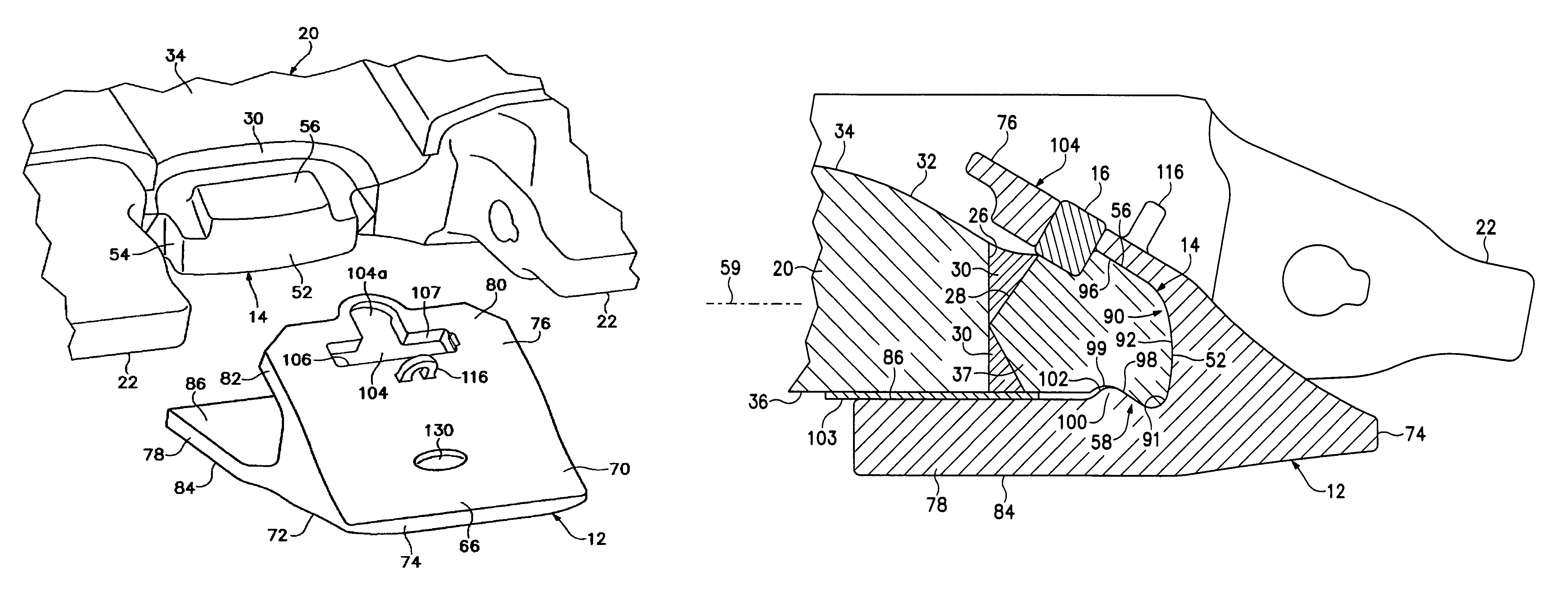
[0008]In accordance with one aspect of the invention, the wear member includes an inwardly projecting support that bears against the base to provide enhanced resistance to back drag and certain vertical loads. The support and base include complementary surfaces that are inclined relative to the central plane of the lip, with the support being rearward of this surface of the base.
[0017]The present inventive system is further able to withstand loads and provide suitable protection with a smaller part as compared to many conventional mechanically attached parts. It enables mechanical attachment of the wear part without the formation of holes in the equipment or reliance on adjacent adapters. Additionally, it does not suffer loss due to unintended loosening of fastening means.

Problems solved by technology

The support then bears against the lower inclined surface of the base during upward vertical loading of the wear member, thus, decreasing the resistance and concomitant stress generated in the upper leg.

Method used


Image

  • Wear assembly for excavating machines
  • Wear assembly for excavating machines
  • Wear assembly for excavating machines

Examples


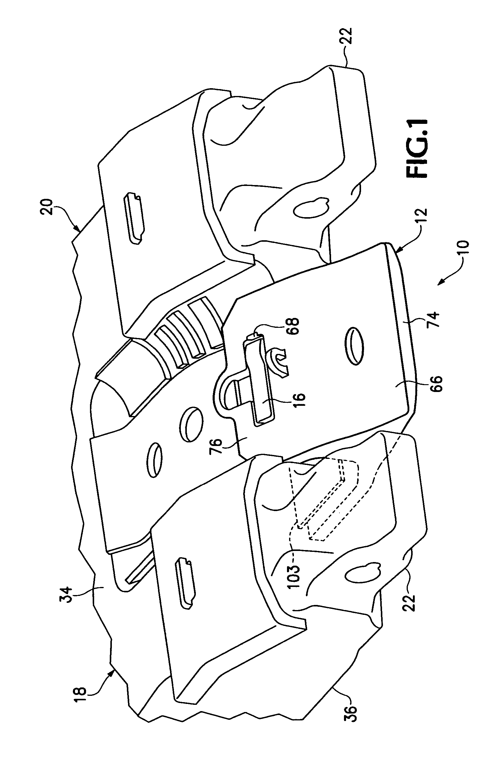
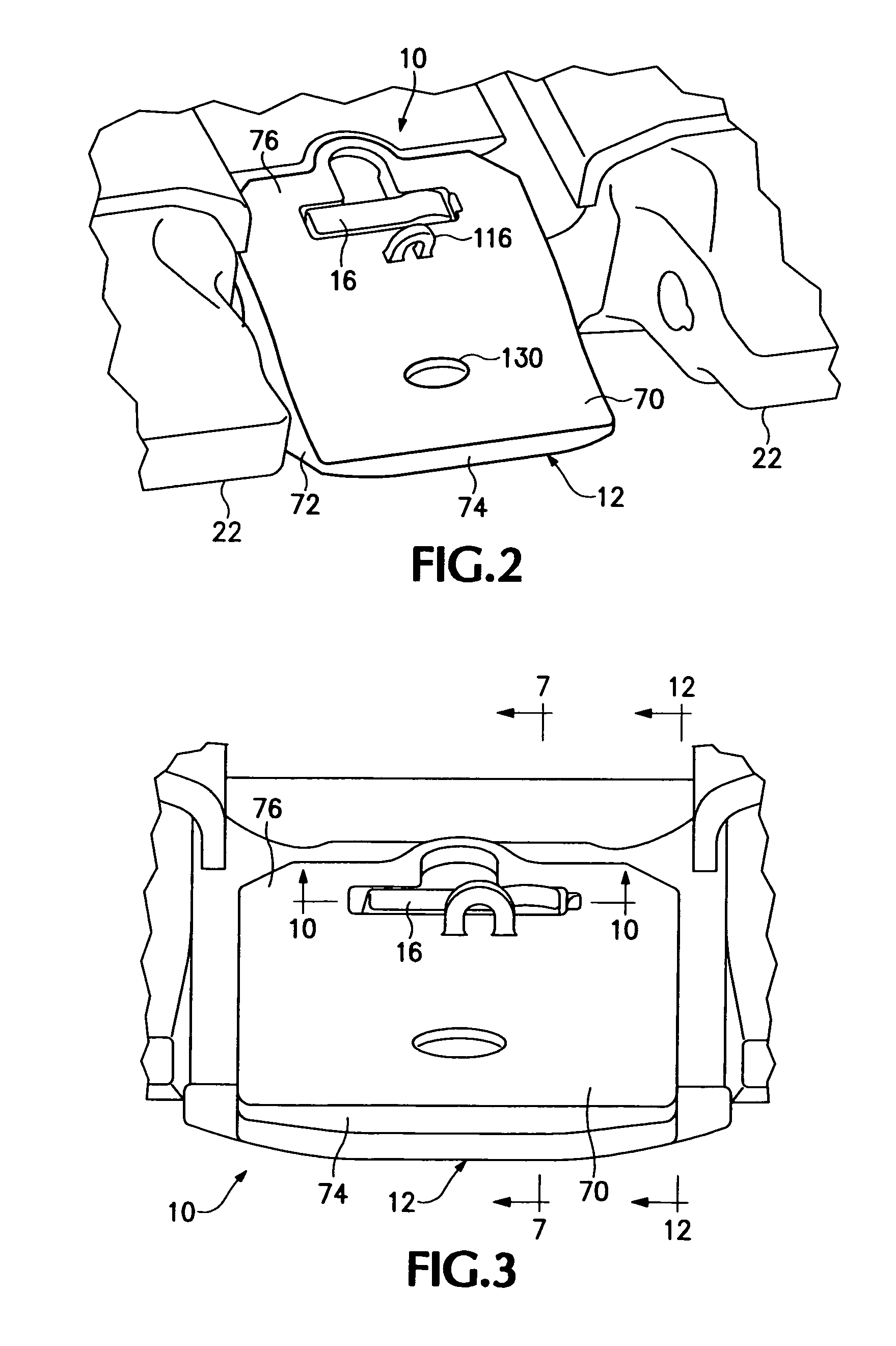
Embodiment Construction

[0030]The present invention pertains to a wear assembly for protecting a digging edge of an excavating machine such as the lip of an excavating bucket. While the assembly is particularly suited for securing a shroud to a lip, the inventive concepts can be used to secure other wear members (e.g., adapters, points, wings and the like) to bucket lips or other excavating equipment. For ease of discussion, this application describes the inventive assembly in terms of mounting a shroud to a bucket.

[0031]A wear assembly 10 in accordance with one embodiment of the present invention includes a wear member 12 in the form of a shroud, a base or support structure 14, and a lock 16 (FIGS. 1-7). A shroud is a wear member that fits over the front edge 17 of an excavating bucket 18, between the excavating teeth, to protect the bucket lip 20 and direct the earthen material into the bucket. FIG. 1 illustrates one example of a lip 20 that includes forwardly projecting noses 22 for supporting points (n...


PUM


Abstract

A wear member that includes a pair of legs defining a slot straddles the digging edge of a piece of excavating equipment. In one construction, the slot is formed at its front end with a pair of inclined surfaces and a laterally extending ridge that is fit within a complementary channel on the digging edge. A lock is received within an opening in the wear member to releasably secure the wear member to the digging edge.

Description

[0001]The present application is co-pending of U.S. provisional application Ser. No. 60 / 712,915, filed Aug. 30, 2005 and of co-pending U.S. provisional application Ser. No. 60 / 758,179, filed Jan. 10, 2006.FIELD OF THE INVENTION[0002]The present invention pertains to a wear assembly for use along the digging edge of an excavating machine.BACKGROUND OF THE INVENTION[0003]Excavating equipment of all kinds and sizes include various wear parts to protect the front digging edge from damage and wear. As a result, the wear parts are commonly subjected to highly abrasive materials and used under arduous conditions. To withstand the rigors of digging, the wear parts must be securely held to the excavating equipment to prevent their loss during use. Nevertheless, due to the harsh environment, the parts frequently wear out and need replacement.[0004]A myriad of ways for attaching the wear parts have been developed with varying degrees of success in securely holding the parts during digging and ...

Claims


Application Information

Patent Timeline
Patent Type & Authority Patents(United States)
IPC IPC(8): E02F9/28
CPCE02F9/2883E02F9/28
Inventor MCCLANAHAN, ROBERTSTITZEL, ADAM
Owner ESCO GRP LLC
Learn More