

Acoustically treated exhaust centerbody for jet engines and associated methods
a jet engine and centerbody technology, applied in the direction of machines/engines, liquid fuel engines, transportation and packaging, etc., can solve the problems of limiting the frequency range of the chamber, causing significant structural load, etc., and achieve the effect of increasing the ability to withstand thermal stresses
- Summary
- Abstract
- Description
- Claims
- Application Information
AI Technical Summary
Benefits of technology
Problems solved by technology
Method used
Image

Examples
Embodiment Construction
,” one will understand how the features of the present embodiments provide advantages, which include increased ability to withstand thermal stresses.
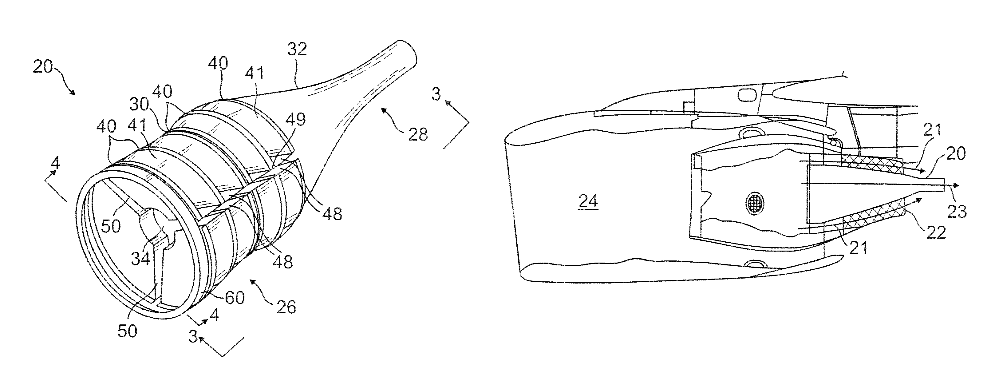
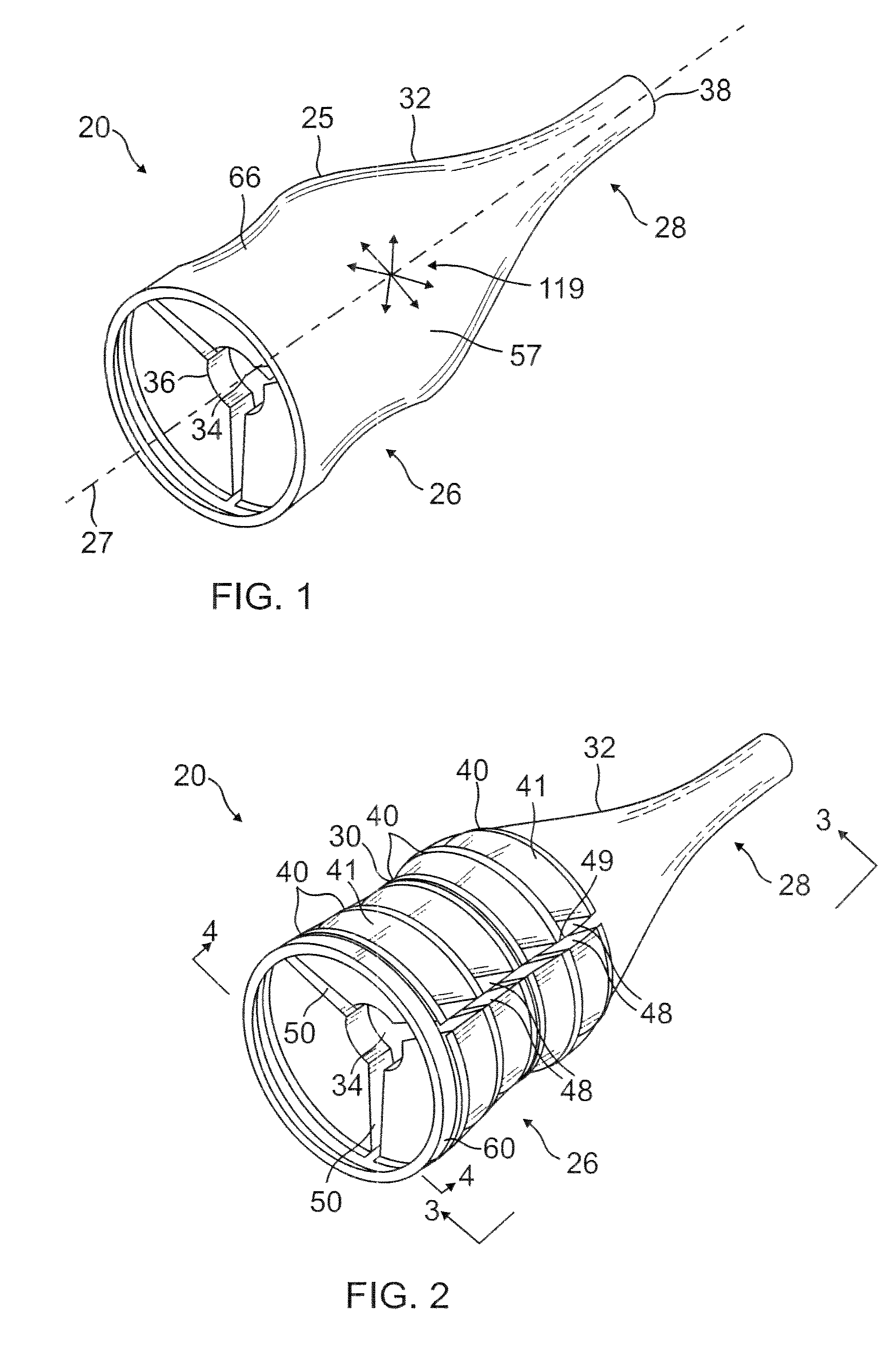
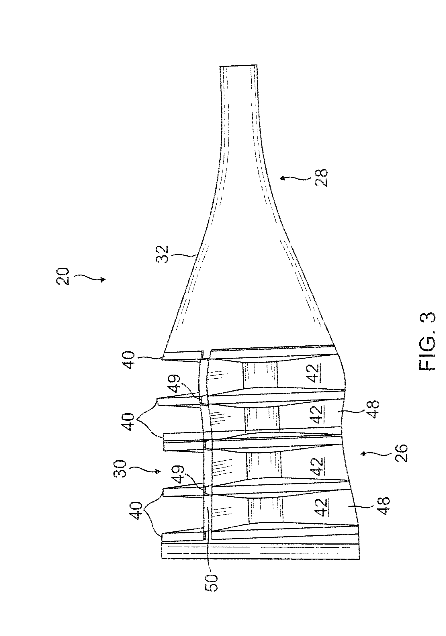
[0007]One aspect of the present acoustically treated exhaust centerbody includes the realization that it would be desirable to increase the depth of the acoustic chamber(s), to broaden the range of attenuated frequencies. In order to increase the depth of the chamber(s), however, the ability of the chamber(s) to withstand thermal stresses must also increase. The present embodiments enable the depth of the chamber(s) to be increased by providing axial (fore / aft) corrugations that enable the resonator to expand and contract axially. Similarly, cavities between adjacent chambers provide circumferential (hoopwise) corrugations that enable the resonator to expand and contract circumferentially and radially. The entire resonator thus acts much like the pleats in an accordion as it expands and contracts under thermal stresses.
[0008]One embodim...
PUM
 Abstract
Description
Claims
Application Information