
Gain enhanced switched capacitor circuit and method of operation

Inactive Publication Date: 2011-09-27
TAIWAN SEMICON MFG CO LTD
View PDF10 Cites 25 Cited by
  • Summary
  • Abstract
  • Description
  • Claims
  • Application Information

AI Technical Summary

Problems solved by technology

In such a gain enhanced switched capacitor circuit, the input is sampled with respect to virtual ground of a closed loops amplifier; however, an inverting configuration (which results in a negative integration) in the sampling phase is utilized.
This, in turn, increases the slew rate requirement of the operational amplifier during transition from the sampling phase to the holding phase, which limits the speed of the circuit.

Method used


Image

  • Gain enhanced switched capacitor circuit and method of operation
  • Gain enhanced switched capacitor circuit and method of operation
  • Gain enhanced switched capacitor circuit and method of operation

Examples


Embodiment Construction

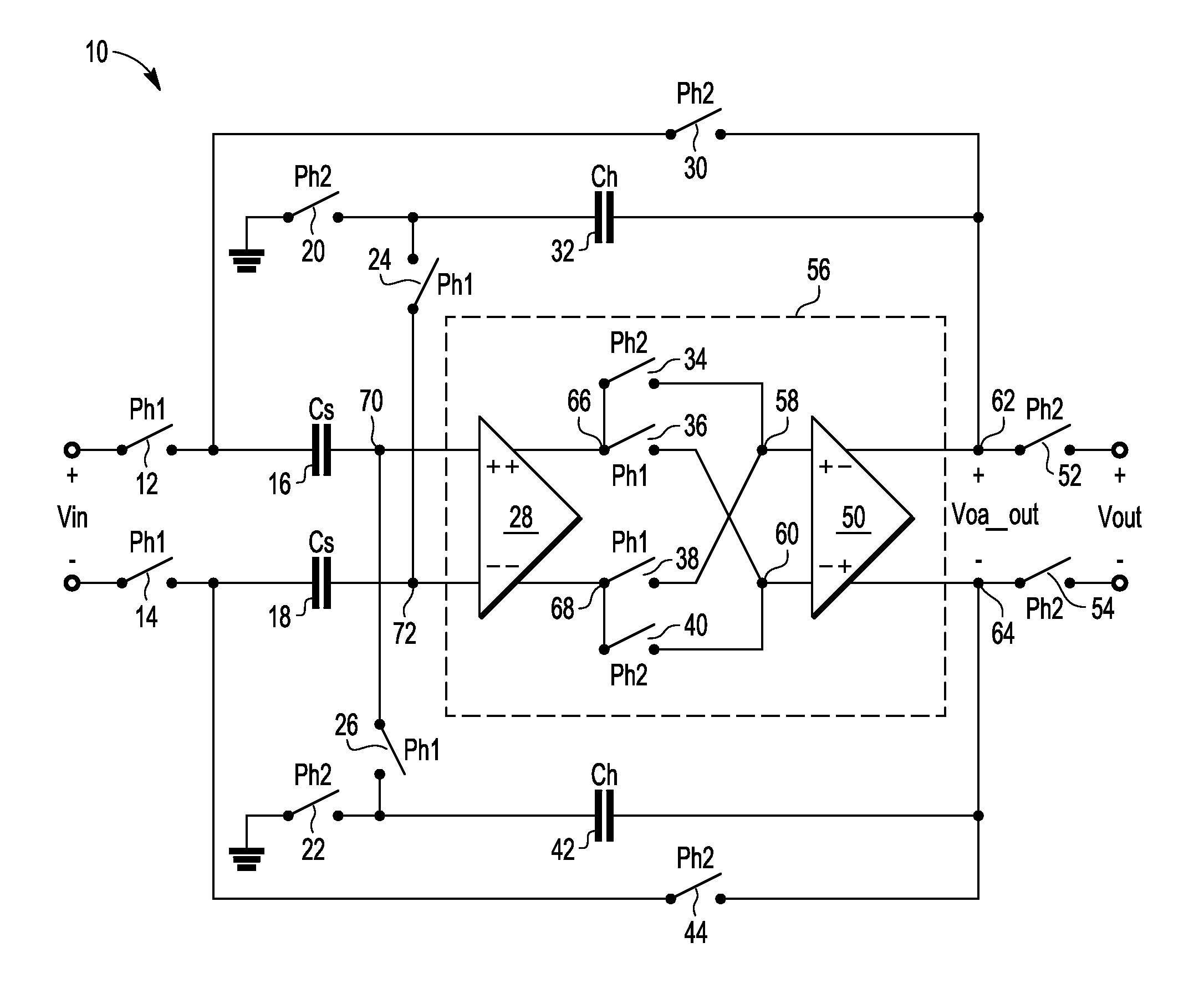
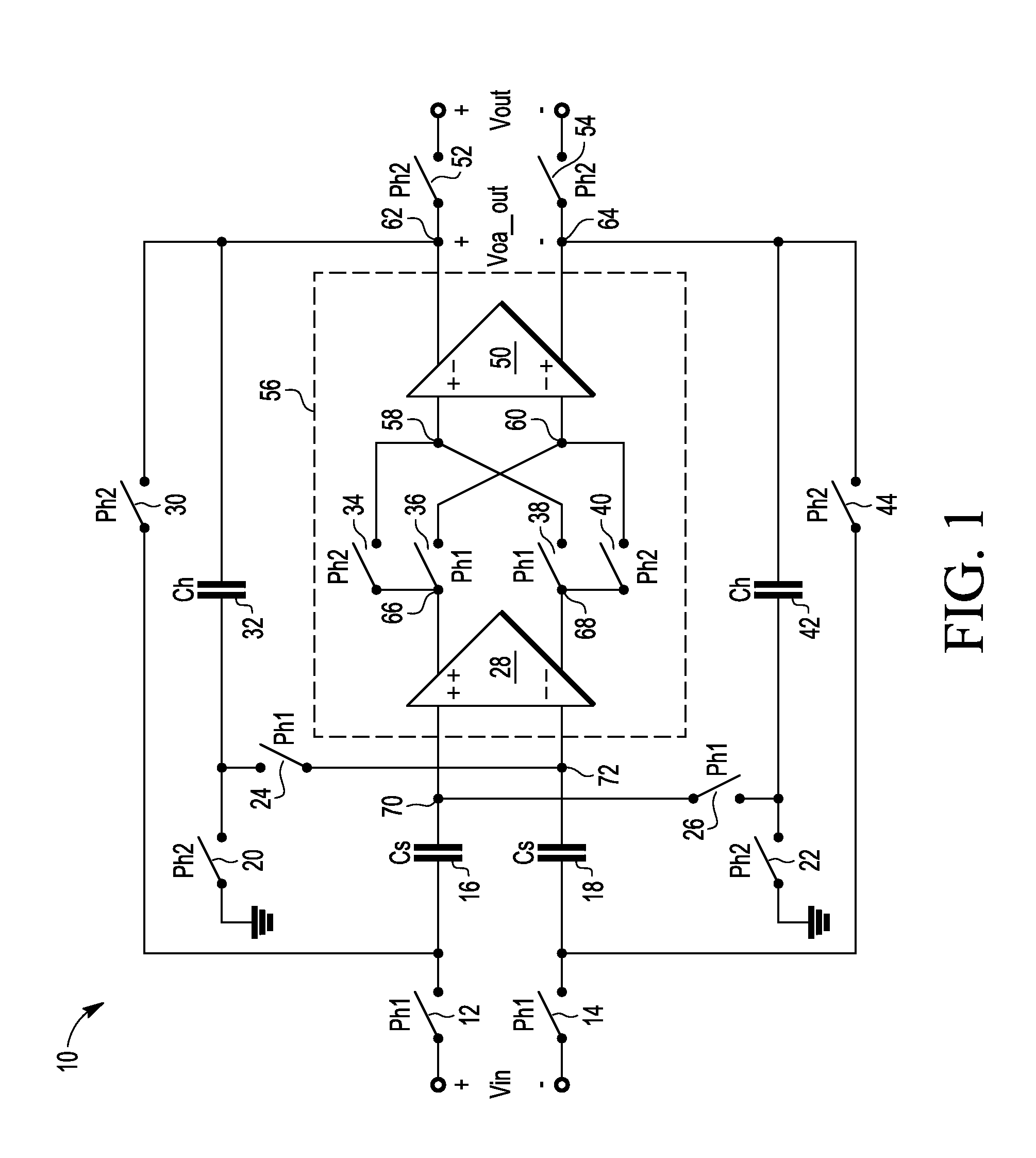
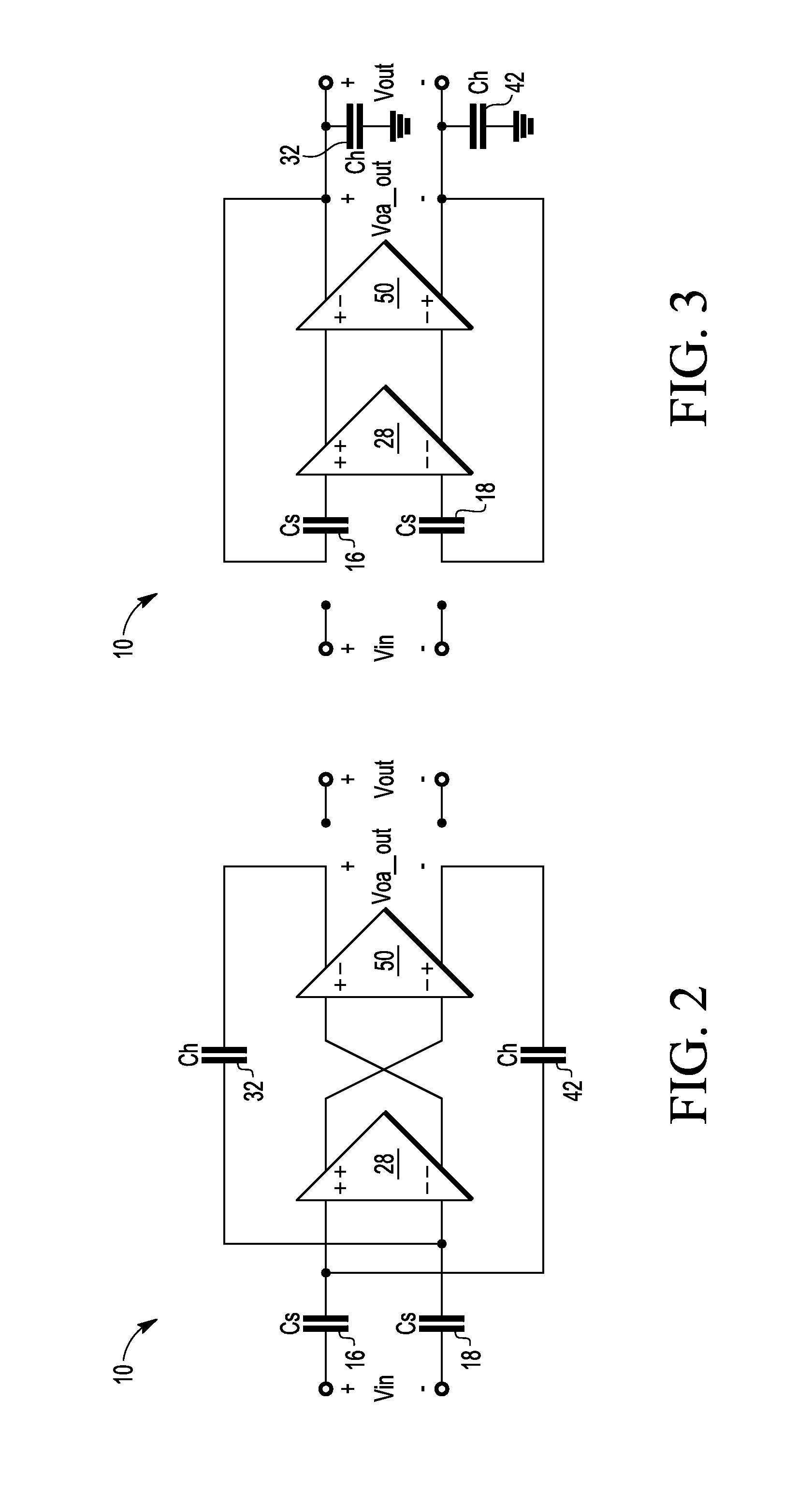
[0013]In one embodiment, a gain enhanced switched capacitor circuit has a differential input and provides a differential output and operates as a sample and hold circuit having a sampling phase and a holding / gain phase. In one embodiment, the gain enhanced switched capacitor circuit is used in a buffer configuration having a sampling phase and a holding phase. In another embodiment, the gain enhanced switched capacitor circuit is used in a gain configuration. In either configuration, during the sampling phase, the input voltage is sampled across the sampling capacitors with respect to virtual ground. In the buffer configuration, during the holding phase, the sampled voltage is held across the operational amplifier. In the gain configuration, during the gain phase, the sampled voltage is amplified. In either configuration, during the sampling phase, the holding capacitors are cross-coupled which allows for the output to track the input. Furthermore, during the sampling phase in eithe...


PUM


Abstract

A switched capacitor circuit utilizes a pair of serially connected differential amplifiers that have plus inputs, minus inputs, plus outputs, and minus outputs. Feedback to the plus / minus inputs is in a first configuration relative to the output of the pair of differential amplifiers in a sampling mode and a second configuration in a hold mode. Similarly, the plus / minus inputs relative to the plus / minus outputs of the serially connected differential amplifiers is reversed between the sampling and hold modes.

Description

BACKGROUND[0001]1. Field[0002]This disclosure relates generally to switched capacitor circuits, and more specifically, to a gain enhanced switched capacitor circuit.[0003]2. Related Art[0004]Switched capacitor circuits are commonly used in mixed signal circuitry, such as to form buffers, gain stages, integrators, etc. For example, a switched capacitor circuit is commonly used within a sample and hold circuit. One type of switched capacitor circuit available today is a gain enhanced switched capacitor circuit. In such a gain enhanced switched capacitor circuit, the input is sampled with respect to virtual ground of a closed loops amplifier; however, an inverting configuration (which results in a negative integration) in the sampling phase is utilized. This negative integration causes the output of the circuit to move in the opposite direction to what is desired. This, in turn, increases the slew rate requirement of the operational amplifier during transition from the sampling phase t...

Claims


Application Information

Patent Timeline
IPC IPC(8): H03F1/02
CPCH03F3/005H03F3/45475H03F2200/411H03F2203/45512H03F2203/45514H03F2203/45534H03F2203/45544H03F2203/45551H03F2203/45582H03F2203/45616H03F2203/45631H03F2203/45644H03F2203/45724H03F2203/45726
Inventor PRASAD, AMMISETTI V.
Owner TAIWAN SEMICON MFG CO LTD
Learn More