
Power generating apparatus

a power generation apparatus and power generation technology, applied in the direction of electric generator control, process and machine control, instruments, etc., can solve the problems of inability to control the output of the generator with the same method, the output of the generator may decrease, and the inability to increase the output of the generator. , to achieve the effect of accurately performing control, reducing the amount of arithmetical processing, and simplifying control

Active Publication Date: 2011-09-27
MAHLE INT GMBH
View PDF8 Cites 18 Cited by
  • Summary
  • Abstract
  • Description
  • Claims
  • Application Information

AI Technical Summary

Benefits of technology

The present invention provides a power generating apparatus that can easily control the voltage and phase of the control voltage to bring the load voltage close to a target value, regardless of the speed of the AC generator, temperature of the winding and switch elements, and other parameters. This is achieved by a controller that includes a voltage accumulating means and control-voltage-phase controlling means for setting the voltage across the load as close to the target value as possible. The controller also includes voltage-phase and current-phase detecting means for accurately detecting the phase of the voltage and current in the AC generator, and a phase-difference detecting means for detecting the phase difference between the voltage and current. This allows for precise control of the load voltage, regardless of the generator's speed or temperature. The invention simplifies the control process, reduces the need for high-performance microprocessors, and improves mass productivity and cost-effectiveness.

Problems solved by technology

However, when the generator is a magnet type AC generator, since a magnetic field is formed by a permanent magnet, it is impossible to control a power generation output with a method same as that in controlling the generator having the magnetic field winding.
However, it is not always possible to increase the output of the generator if the phase of the control voltage with reference to the reference phase is delayed.
If the phase of the control voltage is excessively delayed, the output of the generator may decrease.
However, if the phase of the control voltage is excessively delayed, a power generation output will fall according to the delay in the phase of the control voltage and the capability of the generator cannot be utilized to the maximum.
In the power generating apparatus disclosed in Japanese Patent Application Laid-Open Publication No. 2004-173482, since it is necessary not only to store a large number of data forming the map for limit delay phase arithmetical operation in the memory of the controller but also to store a peculiar parameter every time a specification or an application of the generator is varied, there is a problem in that the controller lacks general versatility.
When the controller lacks general versatility, since mass-productivity of the power generating apparatus is deteriorated, an increase in cost of the power generating apparatus is inevitable because it is necessary to use the high-performance microprocessor.
However, in such a case, the apparatus can have a problem that the capability of the generator cannot be sufficiently utilized.

Method used


Image

  • Power generating apparatus
  • Power generating apparatus
  • Power generating apparatus

Examples


Embodiment Construction

[0057]Preferred embodiments of the present invention are explained in detail below with reference to the accompanying drawings.

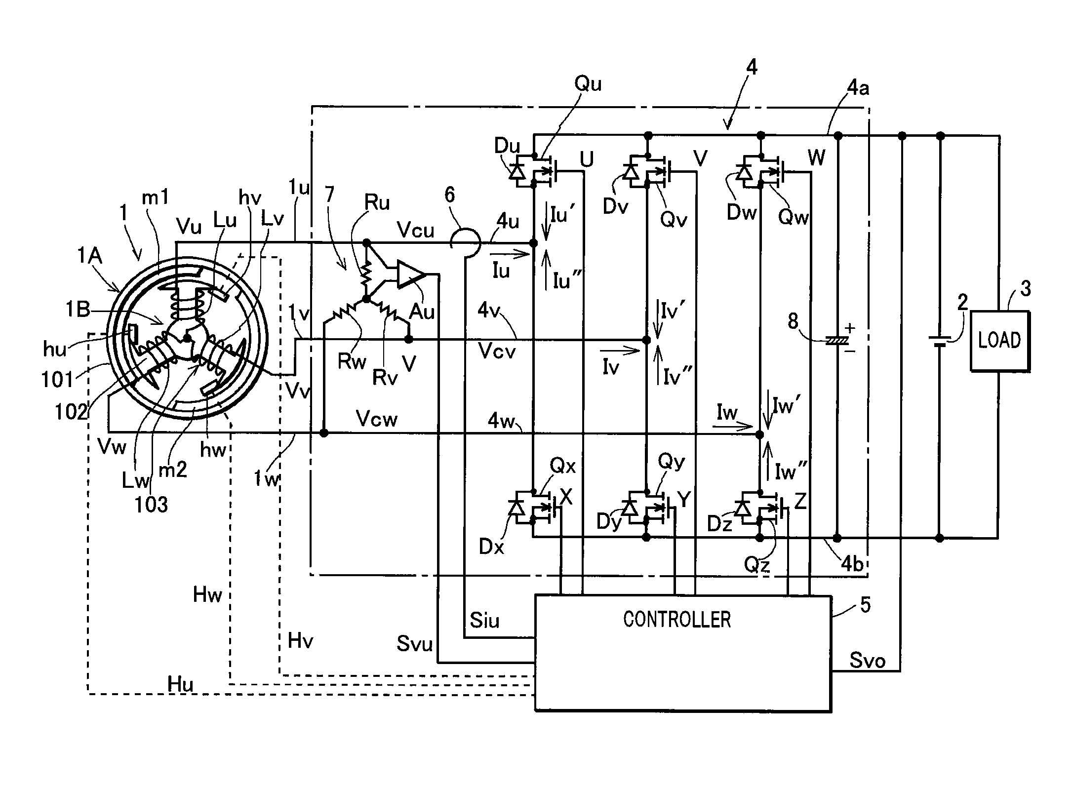
[0058]FIG. 1 is a circuit diagram of a construction of a power generating apparatus according to a preferred embodiment of the present invention. In the figure, a reference numeral 1 denotes a magnet type AC generator driven by an engine, and 2 denotes a battery serving as voltage accumulating means. The battery is also a load of the generator. A reference numeral 3 denotes an external load connected across the voltage accumulating means 2, 4 denotes a voltage source inverter of a bridge type provided between the magnet type AC generator 1 and the voltage accumulating means 2, 5 denotes a controller that controls the inverter, 6 denotes a current detector that detects a phase current of the magnet type AC generator 1, 7 denotes a voltage detection circuit that detects a phase voltage of the magnet type AC generator 1, and 8 denotes a capacitor connected betw...


PUM


Abstract

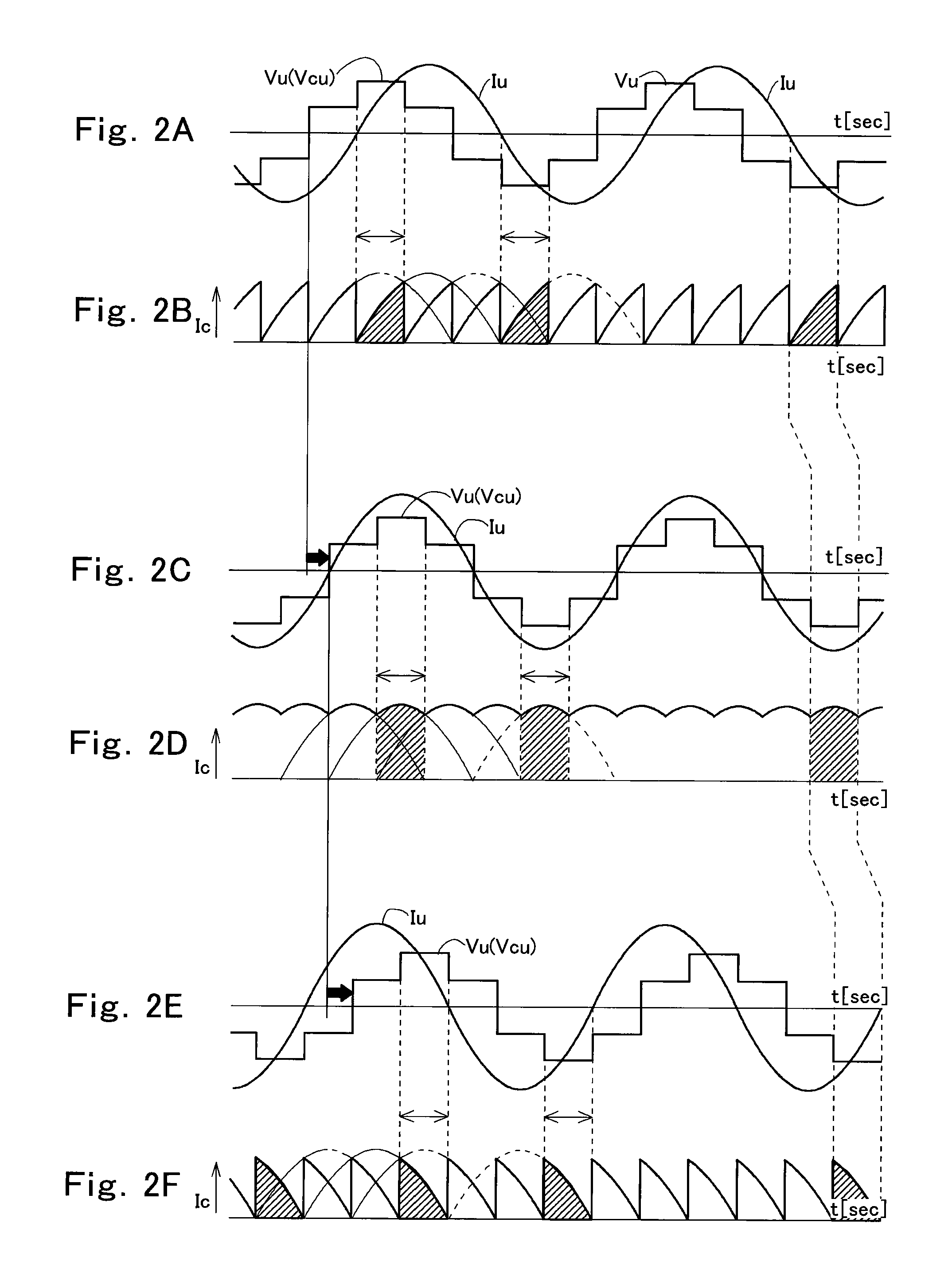
A power generating apparatus including an AC generator that supplies electric power to a load including a voltage accumulating means, an inverter that applies AC control voltage to armature winding of the generator from the voltage accumulating means, and a controller that controls a phase of control voltage applied to the armature winding by the inverter to keep load voltage at a target value, wherein the phase of the control voltage is controlled so as to advance when the load voltage is higher than the target value, hold the present phase when the load voltage is equal to the target value, advance when the load voltage is lower than the target value and a phase of phase voltage of the generator is delayed behind a phase of a phase current of the same phase, and delay when the load voltage is lower than the target value and the phase of the phase voltage of the generator is advanced ahead of a phase of a phase current of the same phase.

Description

TECHNICAL FIELD OF THE INVENTION[0001]The present invention relates to a power generating apparatus that drives a load with a rectified output of an AC generator.PRIOR ART OF THE INVENTION[0002]When a load is driven by a rectified output of an AC generator, it is necessary to control an output of the generator to bring the voltage across the load (load voltage) close to a target value. For example, when a battery is charged by the rectified output of the AC generator, the output of the generator is controlled to keep the voltage across the battery near a target value equivalent to a control value set to prevent the battery from being overcharged.[0003]When the generator has a magnetic field winding, it is possible to control the output of the generator by controlling a magnetic field current. However, when the generator is a magnet type AC generator, since a magnetic field is formed by a permanent magnet, it is impossible to control a power generation output with a method same as th...

Claims


Application Information

Patent Timeline
Patent Type & Authority Patents(United States)
IPC IPC(8): G05F1/40G05F1/44G05F1/455
CPCH02P9/48
Inventor NAKAGAWA, MASANORI
Owner MAHLE INT GMBH
Learn More