Robotic watering unit

a robotic and watering technology, applied in the direction of vehicle position/course/altitude control, process and machine control, instruments, etc., can solve the problem that the type of irrigation system is insufficient for yards and gardens

Active Publication Date: 2011-10-04
DEERE & CO
View PDF18 Cites 58 Cited by
  • Summary
  • Abstract
  • Description
  • Claims
  • Application Information

AI Technical Summary

Problems solved by technology

This type of irrigation system can be inadequate for yards and gardens where numerous species are growing in close proximity, particularly large water users like trees and shrubs in proximity to lesser water users.

Method used


Image

  • Robotic watering unit
  • Robotic watering unit
  • Robotic watering unit

Examples


Embodiment Construction

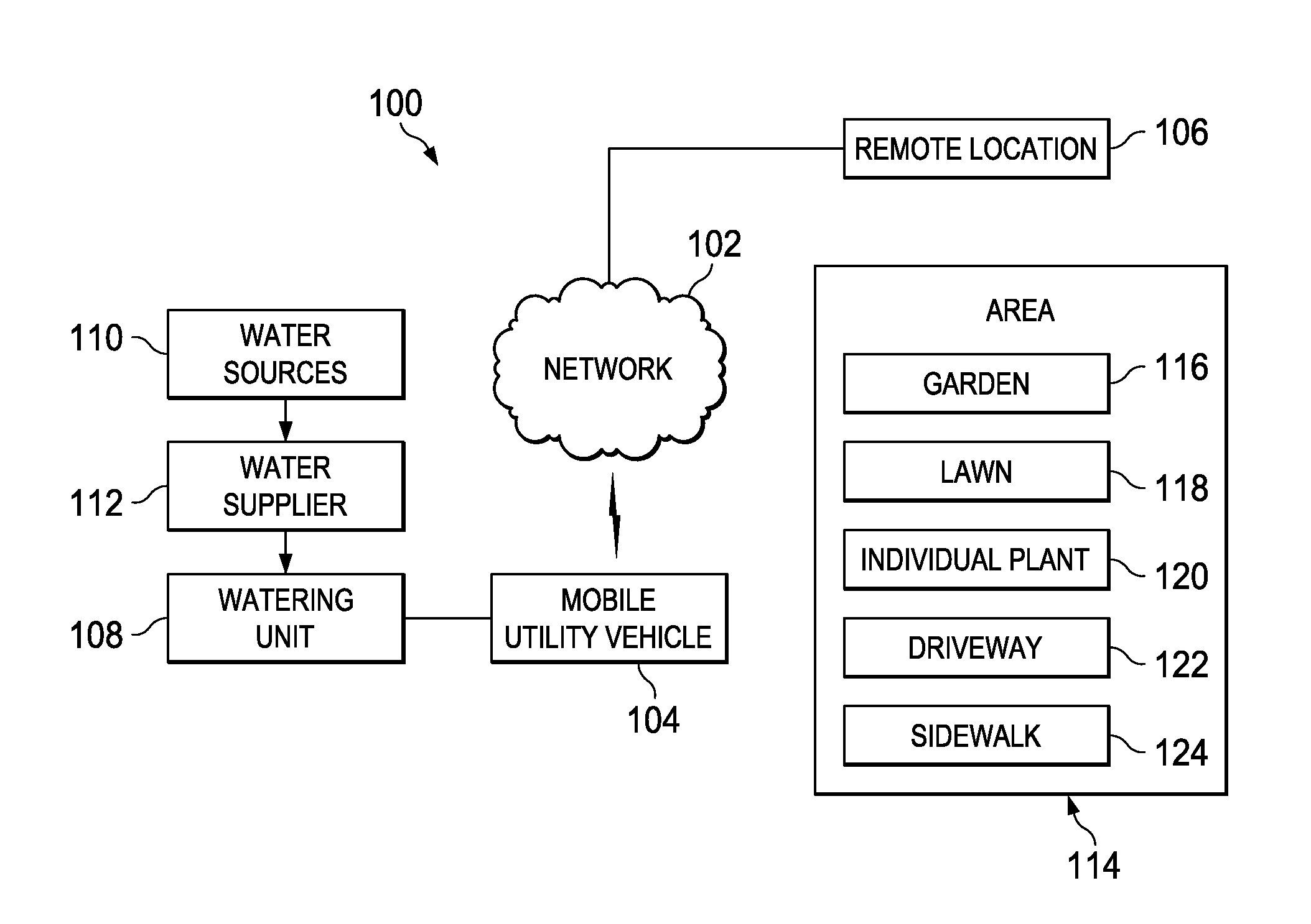
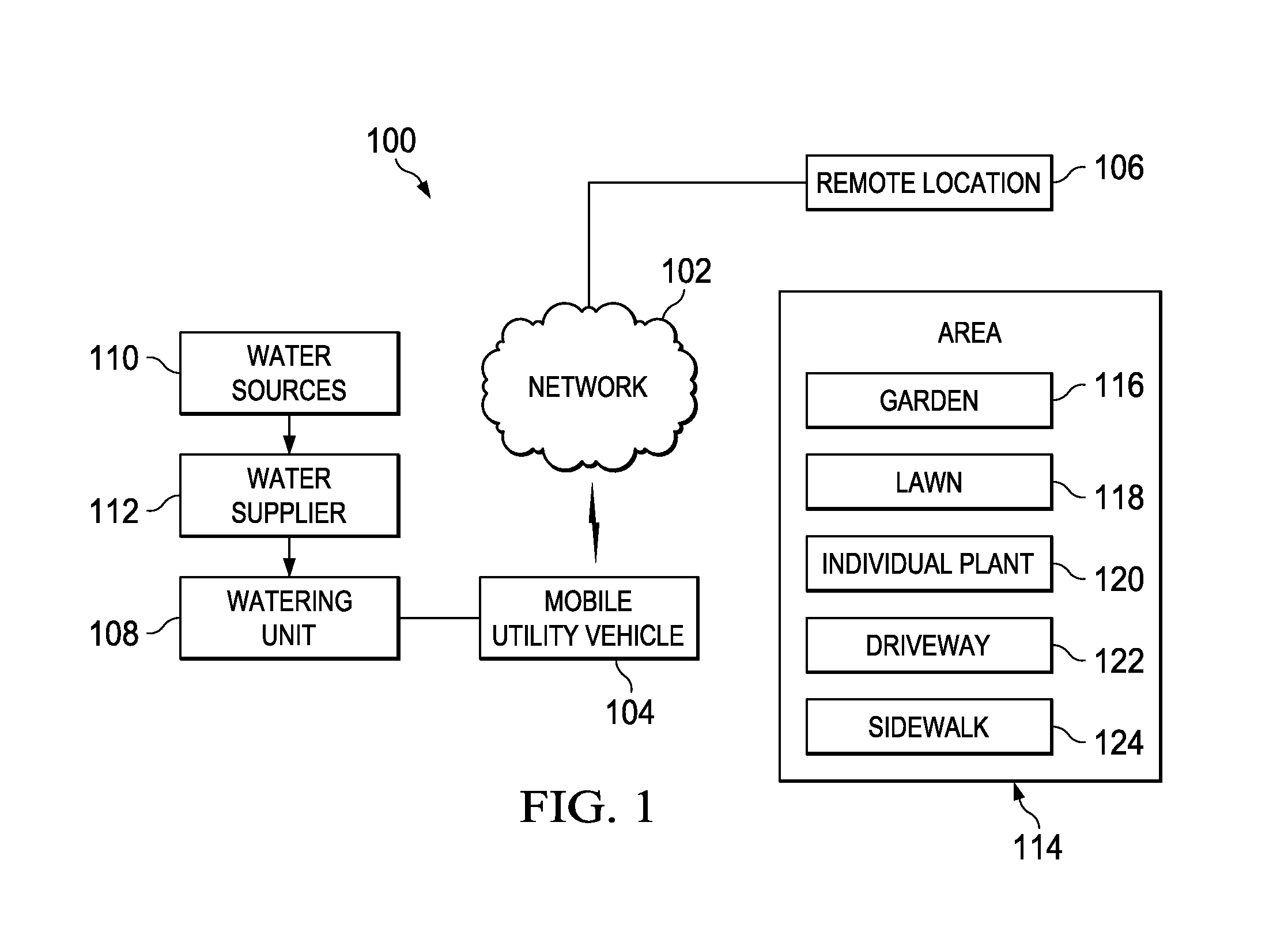
[0016]FIG. 1 is a block diagram of a robotic watering system in which an illustrative embodiment may be implemented. Robotic watering system 100 may be implemented in a network of computers in which the illustrative embodiments may be implemented. Robotic watering system 100 contains network 102, which is the medium used to provide communications links between various devices and computers connected together within robotic watering system 100, such as mobile utility vehicle 104, remote location 106 and watering unit 108. Network 102 may include connections, such as wire, wireless communication links, or fiber optic cables.

[0017]In the depicted example, mobile utility vehicle 104 connects to network 102 in a wireless configuration while remote location 106 has a hard connection to network 102. In another illustrative embodiment, both mobile utility vehicle 104 and remote location 106 may connect to network 102 in a wireless configuration. Remote location 106 may be, for example, pers...


PUM


Abstract

The different illustrative embodiments provide a method and system for watering plants. A map of an area is received and a determination is made using a processing unit as to whether the area needs water. If the area needs water, current constraints are identified and a determination is made using the processing system as to whether the current constraints allow for watering. If the current constraints allow for watering, a watering solution application plan is generated using the processing system, and the watering solution application plan is executed using a mobile utility vehicle.

Description

CROSS REFERENCE TO RELATED APPLICATIONS[0001]This application is related to commonly assigned and co-pending U.S. patent application Ser. No. 12 / 427,051, entitled “A Method for Providing an Application to Plants”; U.S. patent application Ser. No. 12 / 427,059 entitled “Horticultural Knowledge Base for Managing Yards and Gardens”; U.S. patent application Ser. No. 12 / 427,076, entitled “Resource Use Management”; U.S. patent application Ser. No. 12 / 427,043, entitled “System and Method for Managing Resource Use”; all filed on Apr. 21, 2009, and all of which are hereby incorporated by reference.FIELD OF THE INVENTION[0002]The present invention relates generally to an irrigation control system and, more particularly, to a system and method for watering plants in yards and gardens.BACKGROUND OF THE INVENTION[0003]Irrigation is typically used to water large, homogeneous areas such as fields, lawns, and gardens. The water is assumed to be available from a single source, such as a well, canal, o...

Claims


Application Information

Patent Timeline
Patent Type & Authority Patents(United States)
IPC IPC(8): A01G25/09
CPCA01G25/09A01G25/167
Inventor ANDERSON, NOEL WAYNE
Owner DEERE & CO
Why Eureka
Try Eureka