Pressure-reducing valve

a technology of pressure reducing valve and piston, which is applied in the direction of fluid pressure control, container discharge methods, instruments, etc., can solve the problems of lowering the regulation accuracy of gas pressure and interfering with the movement of the piston, and achieves high-precision pressure regulation and prevents the axial displacement of the piston

Inactive Publication Date: 2011-10-04
JTEKT CORP
View PDF16 Cites 2 Cited by
  • Summary
  • Abstract
  • Description
  • Claims
  • Application Information

AI Technical Summary

Benefits of technology

[0010]To solve the above problems, it is an object of the present invention so provide a pressure reducing valve that prevents a seal from being caught in a gap and enables highly accurate pressure regulation.
[0013]Each of the above structures enables the inner circumferential surface of the mating portion to slide in contact with the circumferential wall of the accommodating groove so as to arrange the nut coaxially with the piston. This enables the nut including the mating portion to have an outer diameter set substantially equal to the outer diameter of the piston. The seal is held between the mating portion and the accommodating groove so that the slide piece of the seal is prevented from being caught in a gap. Further, the nut has an outer diameter set substantially equal to the outer diameter of the piston. This increases the surface that slides in contact with the cylinder, and consequently prevents axial displacement of the piston. As a result, the piston moves smoothly, and the pressure reducing valve enables highly accurate pressure regulation.
[0015]This structure arranges the fixing member coaxially with the piston irrespective of backlash of the nut. This enables the fixing member to have an outer diameter set substantially equal to the outer diameter of the piston and prevents the slide piece from becoming caught in a gap. This further increases the surface that slides in contact with the cylinder and consequently prevents axial displacement of the piston. As a result, the piston moves smoothly, and the pressure reducing valve enables highly accurate pressure regulation.
[0017]This structure coaxially arranges the fixing member for fixing the seal with the piston. This enables the outer diameter of the fixing member to be substantially equal to the outer diameter of the piston, and prevents the slide piece from becoming caught in a gap. This further increases the surface that slides in contact with the cylinder, and consequently prevents axial displacement of the piston. As a result, the piston moves smoothly, and the pressure reducing valve enables highly accurate pressure regulation.

Problems solved by technology

This interferes with movement of the piston.
Even if the piston 76, the threaded portion 80, and the fastening nut 81 are formed in a manner that they are arranged coaxially, the play results in a backlash.
This would interfere with smooth movement of the piston 76 and consequently lower the regulation accuracy of the gas pressure.

Method used


Image

  • Pressure-reducing valve
  • Pressure-reducing valve
  • Pressure-reducing valve

Examples


first embodiment

[0023]A first embodiment of the present invention will now be described with reference to the drawings.

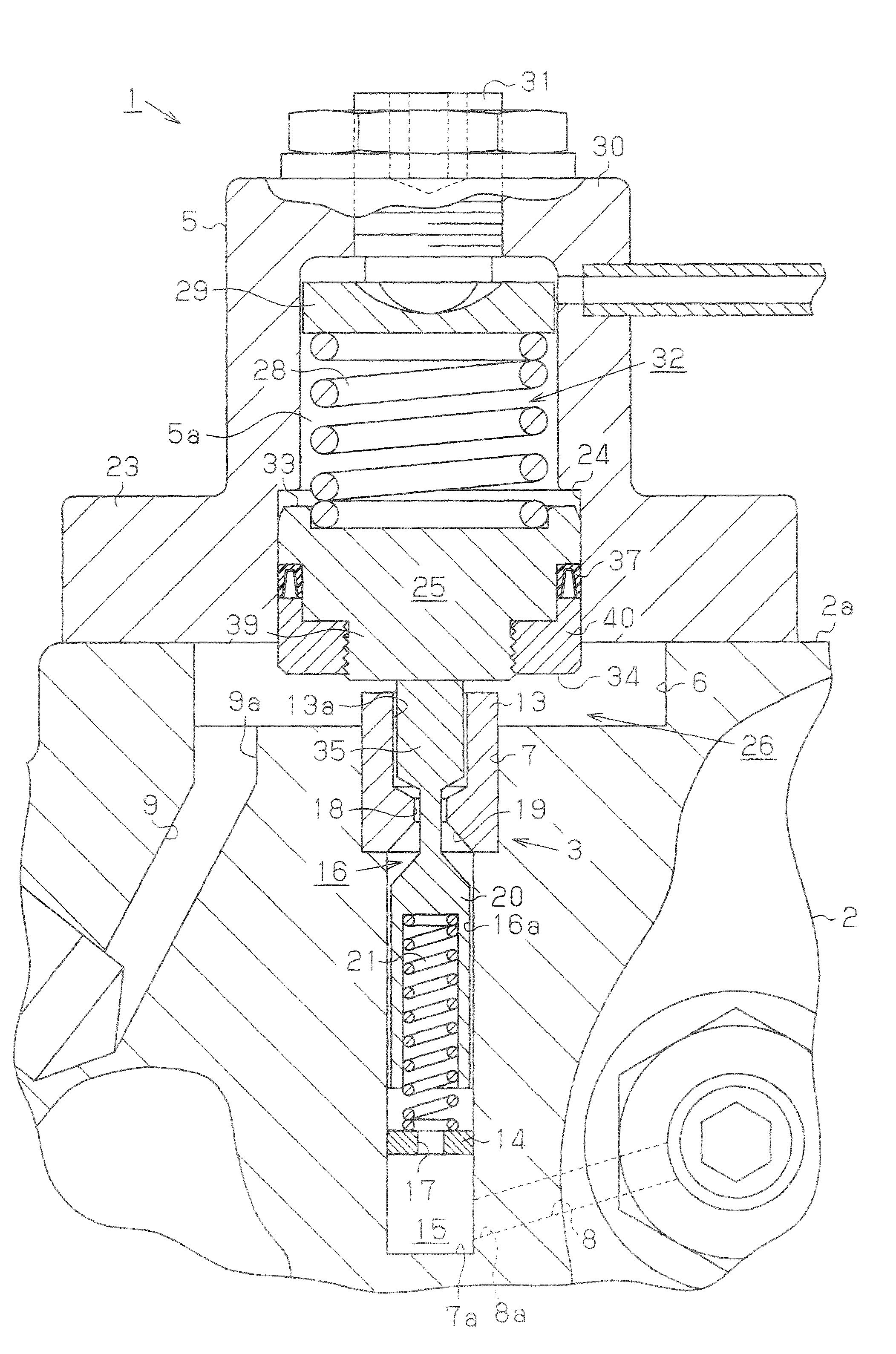
[0024]As shown in FIG. 1, a pressure reducing valve 1 (regulator) of the present embodiment is mounted on a plug housing 2 for closing an opening of a high-pressure hydrogen tank. The pressure reducing valve 1 includes a valve mechanism 3 formed in the plug housing 2 and an outer housing 5 or closing an opening of the plug housing 2.

[0025]The plug housing 2 includes a first recess 6 and a second recess 7, which is arranged in the center of the first recess 6 and is deeper than the first recess 6. An inlet passage 8, which is in communication with the interior of the hydrogen tank, is formed in a side wall in the vicinity of a bottom surface 7a of the second recess 7. An outlet passage 9, which is in communication with an external supply port, is formed in a bottom surface of the first recess 6. In the present embodiment, an inner end of the inlet passage 8 forms a primary port 8a, ...

second embodiment

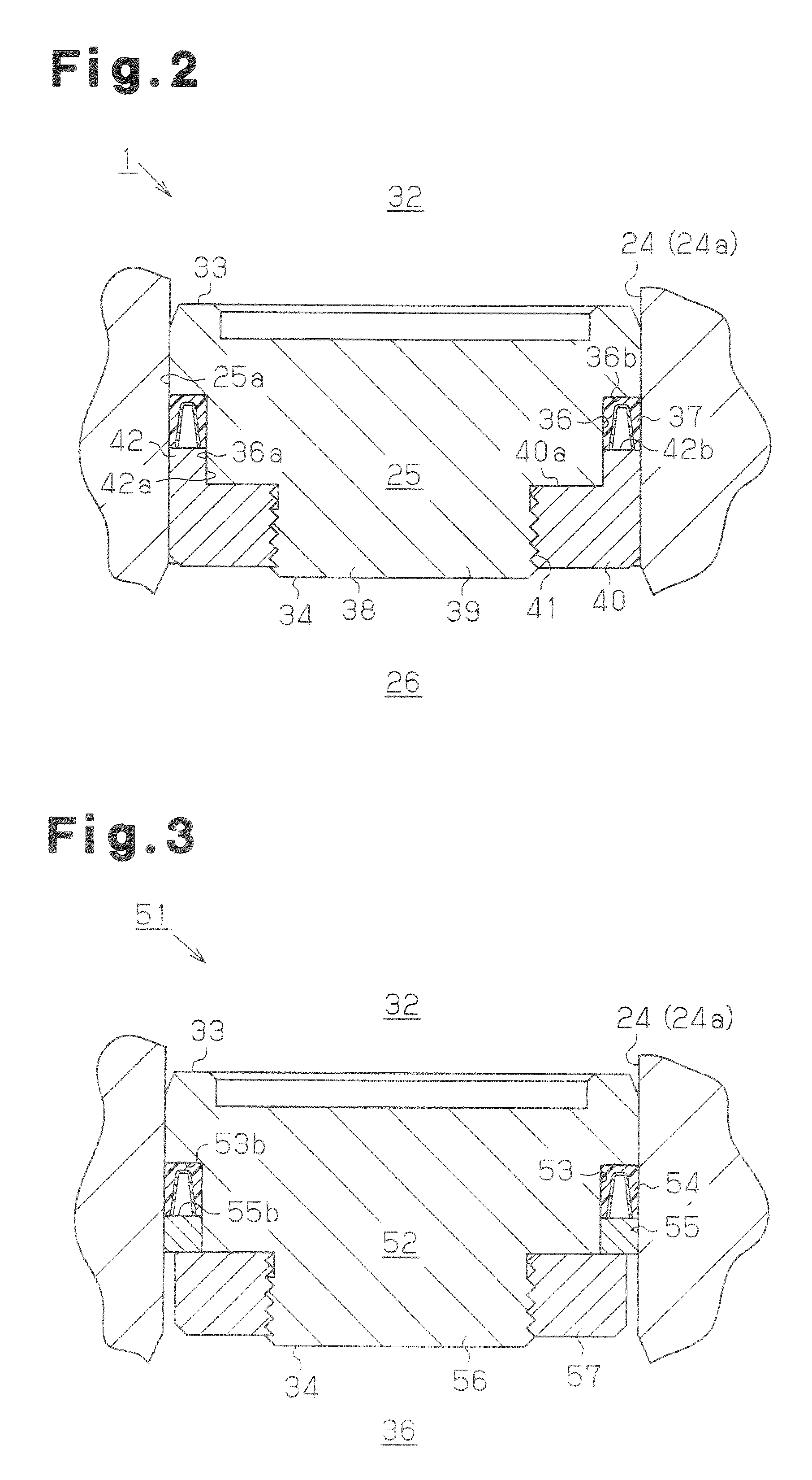
[0043]A second embodiment of the present invention will now be described with reference to the drawings. A pressure reducing valve of the present embodiment differs from the pressure reducing valve 1 of the first embodiment described above only in the structure for fixing the seal of the piston. To facilitate description, the components of the present embodiment that are the same as the components in the first embodiment are given the same reference numerals and will not be described.

[0044]As shown in FIG. 3, a pressure reducing valve 51 of the present embodiment includes a fixing ring 55, which serves as an annular fixing member, fitted in an accommodating groove 53 of a piston 52 together with a lip seal 54. The lip seal 54 is held between the fixing ring 55 and the accommodating groove 53, more specifically, between a contact surface 55b of the fixing ring 55 and a bottom surface 53b of the accommodating groove 53. The inner diameter of the fixing ring 55 is set to be substantial...

third embodiment

[0046]A third embodiment of the present invention will now be described with reference to the drawings. A pressure reducing valve of the present embodiment differs from the pressure reducing valve 1 of the first embodiment described above only in the structure for fixing the seal of the piston. To facilitate description, the components of the present embodiment that are the same as the components in the first embodiment are given the same reference numerals and will not be described.

[0047]As shown in FIG. 4 a pressure reducing valve 61 of the present embodiment includes a press-fitting groove 66, which is in communication with an accommodating groove 65 for accommodating a lip seal 64. The press-fitting groove 66 is formed around a head portion 63 of a piston 62 in the vicinity of a pressure receiving surface 34 of the piston 62. A fixing ring 67, which serves as an annular fixing member, is press-fitted in the press-fitting groove 66. The outer diameter of the fixing ring 67 is sub...


PUM


Abstract

An annular mating portion extends from a fastening surface of a fastening nut. The mating portion has an inner diameter set to be substantially equal to an outer diameter of the portion of a piston in which an accommodating groove is formed. In a state in which the mating portion is inserted into the accommodating groove, and an inner circumferential surface of the mating portion slides in contact with a circumferential wall of the accommodating groove, the fastening nut is mated with a threaded portion, and a lip seal is held between the mating portion and the accommodating groove. This fixes the lip seal to the piston.

Description

FIELD OF THE INVENTION[0001]The present invention relates to a pressure reducing valve used to regulate the pressure of high-pressure gas, such as hydrogen gas for a fuel cell vehicle.BACKGROUND OF THE INVENTION[0002]This type of a pressure reducing valve (regulator) typically includes an open / close valve arranged between a primary port into which high-pressure gas flows and a secondary port from which the gas is discharged. The open / close valve opens and closes to reduce the pressure (primary pressure) of the high-pressure gas flowing through the primary port to a secondary pressure and discharges the gas with the reduced pressure.[0003]In the prior art, such pressure reducing valves include a piston-type pressure reducing valve. The piston-type pressure reducing valve includes a cylinder arranged downstream from an open / close valve and a piston arranged within the cylinder to a slidable manner and defining a pressure reducing chamber and a pressure regulating chamber within the cy...

Claims


Application Information

Patent Timeline
Patent Type & Authority Patents(United States)
IPC IPC(8): F16K31/122
CPCF16K31/122F17C13/04H01M8/04089G05D16/10F17C2205/0323F17C2270/0184Y02E60/321Y02E60/50F17C2205/0326F17C2205/0329F17C2205/0332F17C2205/0338F17C2205/0385F17C2205/0394F17C2221/012F17C2223/0123F17C2223/036F17C2250/0626F17C2260/036F17C2265/065F17C2270/0168G05D16/107Y10T137/7826Y02E60/32
Inventor SUZUKI, TAKUYAFUJIWARA, HIDETOSHISHIMA, TOSHIHIKOKUROYANAGI, MUNETOSHI
Owner JTEKT CORP
Why Eureka
Try Eureka