Constant pressure and variable cleaning angle scraper blade and method for designing same

Inactive Publication Date: 2011-10-04
MARTIN ENG
View PDF4 Cites 10 Cited by
  • Summary
  • Abstract
  • Description
  • Claims
  • Application Information

AI Technical Summary

Benefits of technology

[0010]Accordingly, in the present invention, the scraper blade has a curve which defines a volute of a circle, thereby providing a scraper blade with a longer front surface for a given scraper blade location. The scraper blade includes a blade member having a front surface which includes three curve sections each having three distinct cleaning angles. In particular, the scraper blade provides a distal curve section, an intermediate curve section and a proximate curved section. In one embodiment the angle of the distal curve section, intermediate curve section and the proximal curve section are 50, 45 and 40 degrees, respectively. In one embodiment, each of the three cleaning angle sections is used for approximately 15 degrees of rotation before wearing down to the next cleaning angle section. Thus the total rotation for full wear of the three cleaning angle sections is 45 degrees. The present invention anticipates other cleaning angle combinations. In addition, the present invention anticipates other rotation angles other than 45 degrees. For example, rotation angles from 20 degrees to 45 degrees are included in the rotation angles for pre-cleaner applications with urethane as the wear material. The goal is to maximize the percentage of the urethane blade volume for wear than the connecting or mounting means. The present invention is particularly suited for smaller pulley diameters. The angle of rotation for full wear is more a function of efficient utilization of the expensive wear material.
[0012]In one embodiment, the cleaning angles are selected which provide a positive (peeling) rake angle. In another embodiment, the selected cleaning angles provide a negative (scraping) rake angle. The range of angles typically may extend from a negative rake angle of 10 degrees to a positive rake angle of 50 degrees. The selection is based on a variety of factors such as belt condition, splice condition and rotation of the belt cleaner from the belt. The cleaning angle is the tangent angle at the point of contact. The use of a distal edge at a specific point of contact defining the cleaning angle is simple to allow a graphic solution.

Problems solved by technology

This approach produces a curve which is very close to the theoretically correct solution with a small error.

Method used


Image

  • Constant pressure and variable cleaning angle scraper blade and method for designing same
  • Constant pressure and variable cleaning angle scraper blade and method for designing same
  • Constant pressure and variable cleaning angle scraper blade and method for designing same

Examples


Embodiment Construction

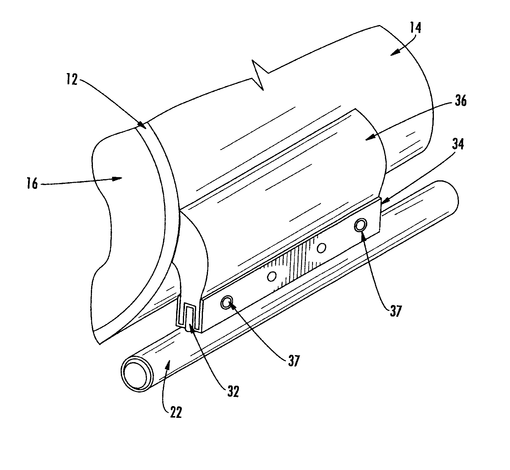
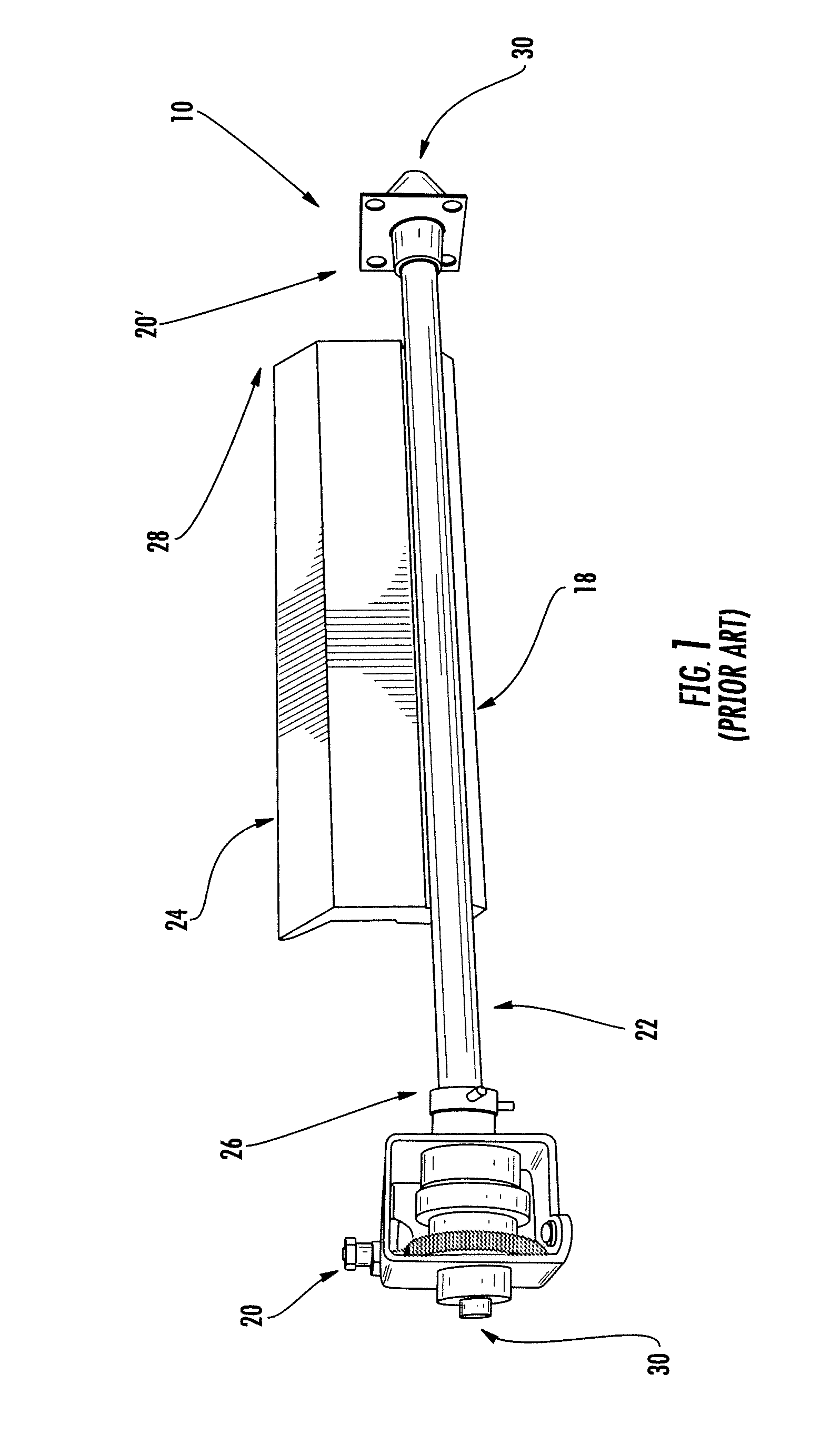
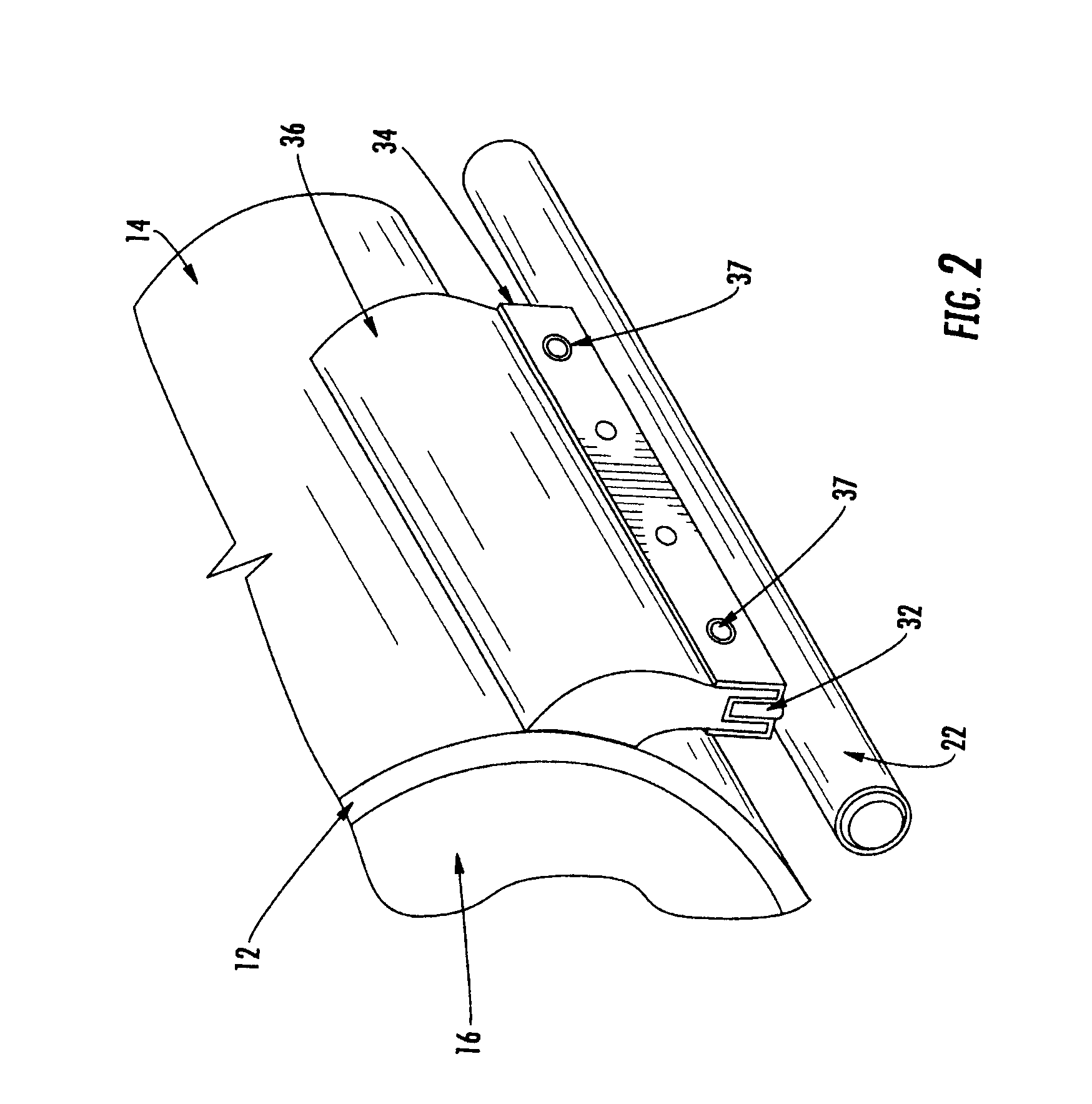
[0043]The conveyor belt cleaner and tensioning arrangement 10, shown in FIG. 1, is adapted for use in connection with a conveyor mechanism. As shown in FIG. 2, the conveyor mechanism includes a rotatable endless conveyor belt 12 having an outer surface 14 that is adapted to transport bulk material. The bulk material is discharged from the conveyor belt 12 at a generally cylindrical head pulley 16 about which the conveyor belt 12 is partially wrapped. The rotatable head pulley 16 and the discharge end of the conveyor belt 12 are located within a conveyor chute which forms part of the conveyor mechanism. The conveyor chute includes a first chute wall and a spaced apart and generally parallel second chute wall. The first and second chute walls form a chamber located therebetween in which the head pulley 16 and discharge end of the conveyor belt 12 are located.

[0044]The conveyor belt cleaner and tensioning arrangement 10 includes a conveyor belt cleaner 18 and one or more conveyor belt ...


PUM


Abstract

A scraper blade for a conveyor belt cleaner is provided. The scraper blade being adapted, when appropriately tensioned against a conveyor belt, to maintain a plurality of predetermined cleaning angles, relative to the conveyor belt, as the scraper blade is progressively worn down through contact with the conveyor belt, the scraper blade having a first blade section and a second blade section. The first blade section is proximate a distal end of the scraper blade, the first blade section being configured to maintain a first predetermined cleaning angle relative to the conveyor belt. The second blade section substantially adjacent the first blade section, the second blade section being configured to maintain a second predetermined cleaning angle, relative to the conveyor belt, after the first blade section is worn away through contact with the conveyor belt. The second predetermined cleaning angle is different than the first predetermined cleaning angle. The first blade section and the second blade section each define a profile which approximately corresponds to a volute of a circle. Processes and computer implemented processes for designing outer profiles and inner profiles of primary scraper blades and secondary scraper blades are also provided.

Description

CROSS-REFERENCE TO RELATED APPLICATIONS[0001]This application claims the benefit of U.S. Provisional Application No. 60 / 824,399, filed Sep. 1, 2006, the entirety of which is hereby incorporated by reference.BACKGROUND OF THE INVENTION[0002]1. Field of the Invention[0003]The present invention relates to scraper blades which are used to remove residual material clinging to the return run of a conveyor belt and, in particular, to primary scraper blades used in pre-cleaner applications located at the head pulley of the conveyor belt. The present invention also relates to processes and methods of designing both primary and secondary scraper blades.[0004]2. Background Art[0005]Scraper blades were previously made such that just the scraping edge of the blade face surface initially engaged the conveyor belt, rather than the entire or full blade face surface, when installed. This edge contact type of blade design cleans with high efficiency when new, but after the blade wears for a short per...

Claims


Application Information

Patent Timeline
IPC IPC(8): B65G45/00B65G45/12
CPCB65G45/16B65G2203/02
Inventor SWINDERMAN, ROBERT TODD
Owner MARTIN ENG
Why Eureka
Try Eureka