Light unit, backlight, frontlight, and display device

a technology of backlights and display devices, applied in lighting devices, lighting and heating devices, instruments, etc., can solve the problems of low luminance at the end portion and light radiation, and achieve the effect of suppressing the even luminance generated in displaying an image and without complicated structur

Inactive Publication Date: 2011-10-04
SHARP KK
View PDF18 Cites 13 Cited by
  • Summary
  • Abstract
  • Description
  • Claims
  • Application Information

AI Technical Summary

Benefits of technology

[0012]Preferred embodiments of the present invention have been developed in view of the above-mentioned problems, and the preferred embodiments of the present invention provide a light unit, a backlight, a frontlight, and a display device, in which uneven luminance generated in displaying an image is suppressed by radiating light in a sufficient amount even to an end portion of a display region, thereby uniformly radiating light in a sufficient amount to the entire display region, without a complicated structure.

Problems solved by technology

It was discovered that an insufficient amount of light is radiated from a plurality of light sources to the end portion of the display region, and therefore the luminance at the end portion is low.

Method used


Image

  • Light unit, backlight, frontlight, and display device
  • Light unit, backlight, frontlight, and display device
  • Light unit, backlight, frontlight, and display device

Examples


first preferred embodiment

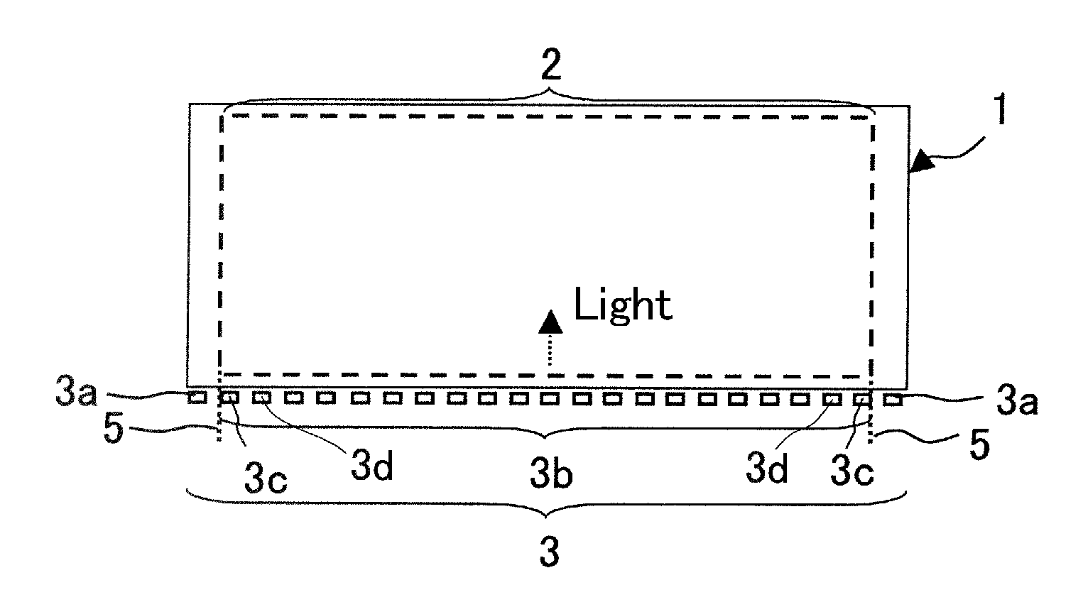
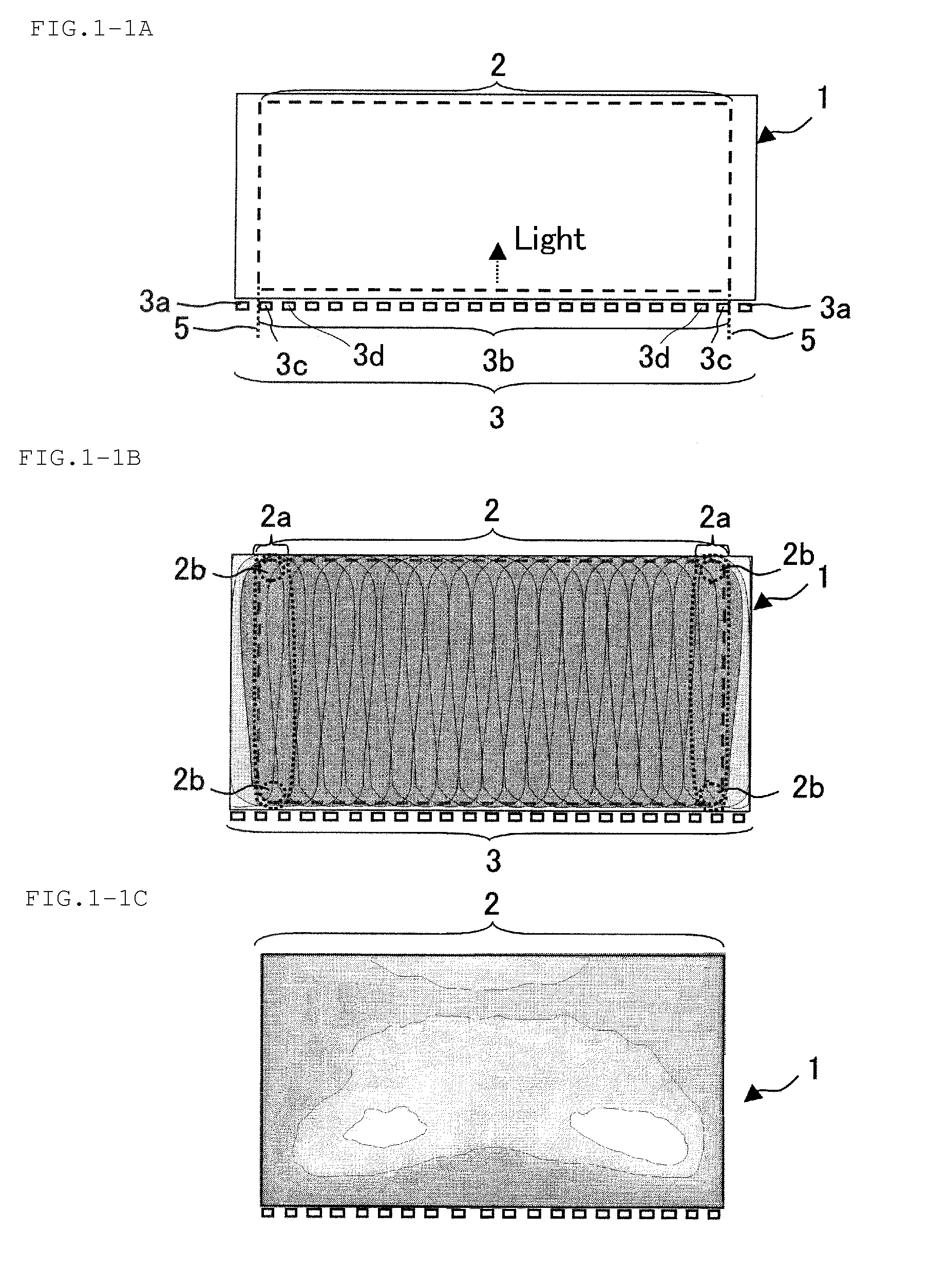
[0054]FIGS. 1-1A to 1-1C are planar views schematically showing an arrangement relationship between light sources and a light guide plate in a light unit in accordance with a first preferred embodiment. FIG. 1-1A schematically shows a configuration of the light unit. FIG. 1-1B schematically shows a state where lights from the light sources overlap with each other on the light guide plate. FIG. 1-1C shows a measurement result of a luminance distribution. As shown in FIG. 1-1A, the light unit in a first preferred embodiment includes a rectangular or substantially rectangular light guide plate 1 and a plurality of light sources 3. The plurality of light sources 3 are arranged in a line to oppose one side surface on the side of a long side of four sides of the light guide plate 1. White LEDs are preferably used as the light sources 3. The use of the white light sources has the following advantages in comparison to the case where a set of light sources such as red (R), green (G), and blu...

second preferred embodiment

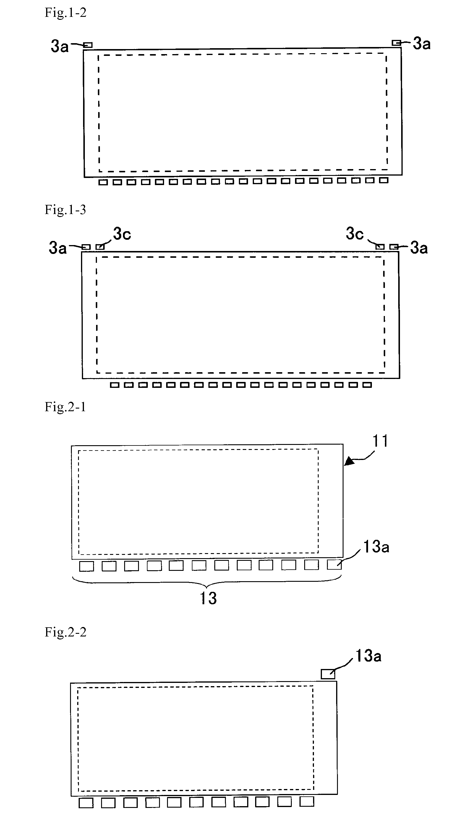
[0061]FIG. 2-1 is a planar view schematically showing a light unit in accordance with the second preferred embodiment. The light unit in the second preferred embodiment is different from that in the first preferred embodiment in that light sources 13a positioned outside the lateral edge of the display region are arranged only at one terminal, not at both terminals of the line where light sources 13 are arranged. The configuration in the second preferred embodiment is obtained just by extending only one side of the light guide plate 11. Accordingly, the second preferred embodiment can be preferably used if an increase in size of the display region is limited or the display device needs to be downsized.

[0062]In the second preferred embodiment, the light sources 13 may not be arranged on one side of the light guide plate 11. Some light sources may be arranged on the opposite side, for example, as shown in FIG. 2-2. FIG. 2-2 shows a preferred embodiment in which the terminal light sourc...

third preferred embodiment

[0063]FIG. 3 is a planar view schematically showing a light unit in accordance with the third preferred embodiment. The light unit in the third preferred embodiment is different from that in the first preferred embodiment in that a plurality of light sources 23 are arranged in one line on side surfaces on the side of both long sides of a rectangular light guide plate 21. Similarly in the first preferred embodiment, generation of uneven luminance in the display region can be suppressed even in the light unit in the third preferred embodiment. As a result, excellent display qualities can be obtained. In addition, the light sources 23 are arranged on the both side surfaces of the light guide plate, and therefore an image with a higher luminance can be displayed.


PUM


Abstract

A light unit, a backlight, a front light, and a display device, have a structure such that an uneven luminance generated in display is suppressed by radiating light in a sufficient amount even to an end portion of a display region, thereby uniformly radiating light in a sufficient amount to the entire display region, without a complicated structure. The light unit includes a light guide plate and a plurality of light sources, the plurality of light sources being arranged in a line to oppose at least one side surface of the light guide plate, wherein one or more light sources at at least one terminal among the plurality of light sources are positioned outside a lateral edge of a display region, and such a light unit is preferably used in a side-light type backlight or front light.

Description

BACKGROUND OF THE INVENTION[0001]1. Field of the Invention[0002]The present invention relates to a light-unit, a backlight, a front light, and a display device. More specifically, the present invention relates to a light unit preferably used in a side-light type backlight or front light, and a display device such as a liquid crystal display device, including the light unit.[0003]2. Description of the Related Art[0004]A display device including a non-self-emitting display panel, such as a liquid crystal display panel, needs to include light sources in order to display an image. Reflected sunlight is used as a light source, but a light unit needs to be arranged in the following display devices: a display device which is mainly used indoors such as a word processor, a laptop personal computer, and an in-car liquid crystal display device (LCD); and a display device which is used outdoors but constantly needs a certain light amount.[0005]Side-light type and direct-type backlights and the...

Claims


Application Information

Patent Timeline
Patent Type & Authority Patents(United States)
IPC IPC(8): F21V7/04
CPCG02B6/0068G02F1/133615G02F2001/133616G02F1/133616
Inventor TAKAHASHI, YUHJI
Owner SHARP KK
Why Eureka
Try Eureka