Systems and methods for radio frequency identification
What is Al technical title?
Al technical title is built by PatSnap Al team. It summarizes the technical point description of the patent document.
a radio frequency identification and identification system technology, applied in the field of identification systems, can solve the problems of affecting so as to improve the safety of residents, enhance the investigatory tools, and improve the investigatory potential of the facility.
Active Publication Date: 2011-10-04
SECURUS TECH LLC
View PDF8 Cites 53 Cited by
Summary
Abstract
Description
Claims
Application Information
AI Technical Summary
This helps you quickly interpret patents by identifying the three key elements:
Problems solved by technology
Method used
Benefits of technology
[0012]Embodiments of the present invention provide a reliable and low-cost alternative for identifying residents and controlling actions associated with a controlled environment facility, such as a prison facility (e.g. jail, stockade, prison, penitentiary, etcetera), hospitals, nursing homes, camps, and / or the like. In addition to providing improved security through controlling any or all resident's actions, embodiments of the invention provide enhanced investigatory tools for the controlled environment facility through monitoring and / or recording actions of positively identified residents. Accordingly, embodiments operate to provide increased security for the residents and management of controlled environment facilities while expanding investigatory potential for the facility. Moreover, using systems and methods of the present invention, law enforcement is provided a choice in how security violations are managed within a controlled environment facility.
Problems solved by technology
Often, controlled environment facilities may place different limitations on residents associated therewith with respect to a plurality of activities.
A problem with utilizing a PIN number to identify an inmate for call validation purposes is that a PIN number may be easily traded, sold or stolen within a prison facility.
Accordingly, there is a potential for harassment with calls being made to restricted numbers (e.g., victims, witnesses, judges, etcetera), the coordination of external / internal illegal business operations from within the facility, gang activity being coordinated from within facilities, riots or other activities being coordinated within and between facilities, and / or the general loss of command and control by facility leadership.
In addition to posing a serious security risk, calls placed by inmates utilizing PIN numbers other than their own reduce the effectiveness of a facility's investigatory process.
Method used
Image
Click on the blue label to locate the original text in one second.
Reading with bidirectional positioning of images and text.
Examples
Embodiment Construction
[0028]To aid in understanding of the concepts of the present invention, some embodiments will be described herein with reference to a prison facility. It should be appreciated, however, that the present invention is not limited to application with respect to prison facilities and may readily be applied to a variety of controlled environment facilities, such as hospitals, nursing homes, camps, dormitories, campuses, etcetera.
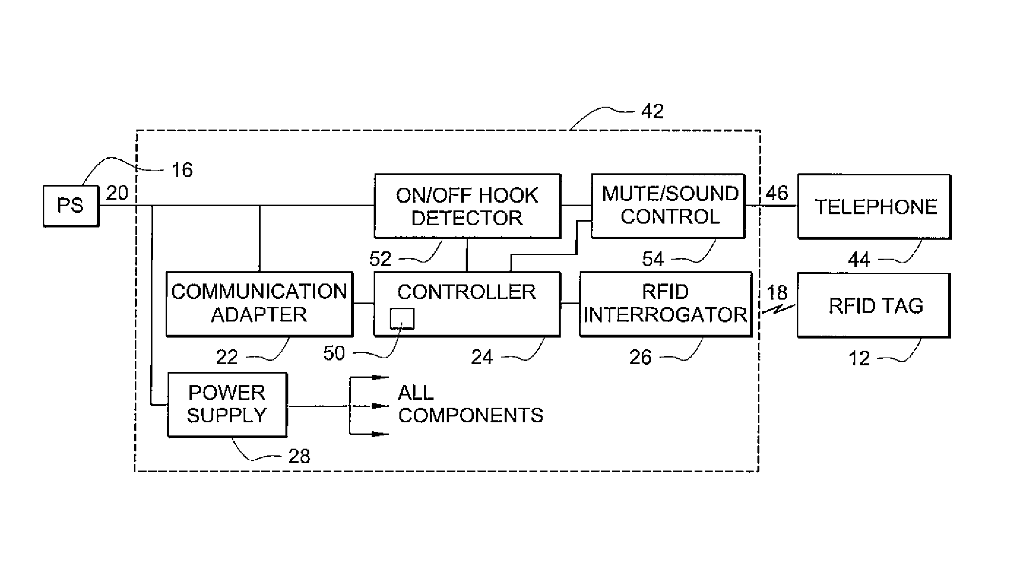
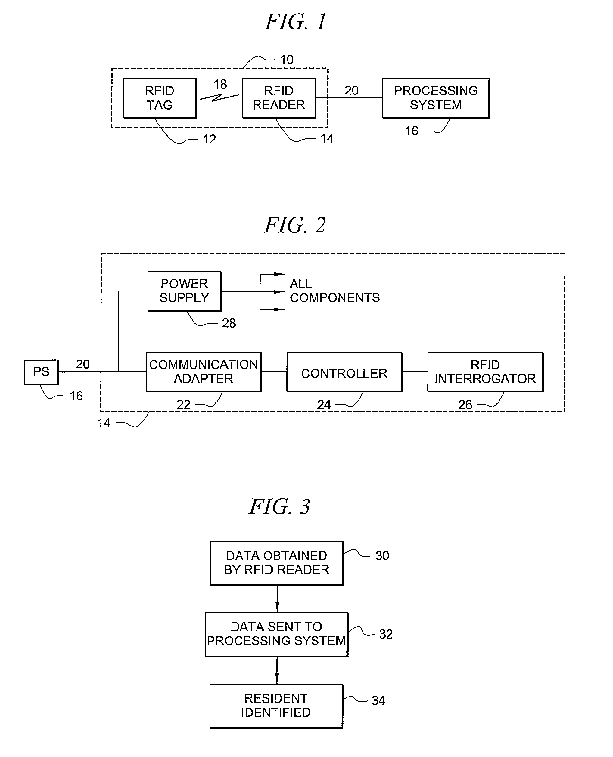
[0029]Directing attention to FIG. 1, a block diagram illustrating a RFID system adapted for use in identifying residents of a controlled environment facility is shown according to an embodiment of the present invention. Specifically, RFID system 10 includes at least one RFID tag 12 and at least one RFID reader 14. RFID tag 12 shown is suitable for affixing securely to a resident of the controlled environment facility, and contains data associated with the resident's identity, such as an identification number. RFID tag 12 is coupled with RFID reader 14 via communi...
PUM
Abstract
Systems and methods providing radio frequency identification (RFID) of individuals, as may be implemented with respect to a controlled environment facility, using RFID transducer technology deployed in association with a user terminal, such as telephone or multimedia kiosk, are shown. Embodiments operate to identify residents of a controlled environment facility and control one or more transactions associated with the residents and / or actions of the residents using a RFID system in which a user presents a RFID transponder in proximity to a RFID transducer for identification. RFID tags of embodiments comprise data which identifies an individual, data which may be used to identify an individual, or a combination of both. RFID systems of embodiments are adapted to utilize existing communication links for identification of individuals using RFID and / or for controlling transactions, such as calls, using RFID.
Description
CROSS-REFERENCE TO RELATED APPLICATIONS[0001]The present application is related to commonly assigned U.S. patent applications Ser. No. 10 / 135,878 entitled “Information Management and Movement System and Method,” filed Apr. 29, 2002, (now abandoned); Ser. No. 11 / 125,842 entitled“Processor-Based Self-Service Terminals Used with Respect to Controlled Environment Facilities,” filed May 10, 2005, Ser. No. 11 / 338,868 entitled “Systems and Methods for Transaction and Information Management,” filed Jan. 24, 2006, Ser. No. 10 / 642,532 entitled “Centralized Call Processing,” filed Aug. 15, 2003,)issued as U.S. Pat. No. 7,899,164); Ser. No. 10 / 701,549 entitled “Systems and Methods for Cross-Hatching Biometrics With Other Identifying Data,” filed Nov. 5, 2003,(issued as U.S. Pat. No. 7,278,028); Ser. No. 11 / 480,335 entitled “Systems and Methods for Multimedia Visitation,” filed Jun. 30, 2006, (now abandoned); and Ser. No. 11 / 480,259 entitled “System and Method for Electronic Visitation Registrat...
Claims
Application Information
Patent Timeline
Application Date:The date an application was filed.
Publication Date:The date a patent or application was officially published.
First Publication Date:The earliest publication date of a patent with the same application number.
Issue Date:Publication date of the patent grant document.
PCT Entry Date:The Entry date of PCT National Phase.
Estimated Expiry Date:The statutory expiry date of a patent right according to the Patent Law, and it is the longest term of protection that the patent right can achieve without the termination of the patent right due to other reasons(Term extension factor has been taken into account ).
Invalid Date:Actual expiry date is based on effective date or publication date of legal transaction data of invalid patent.