Three-piece lower manifold for a V-style engine intake manifold

a technology of v-style engine and intake manifold, which is applied in the direction of machines/engines, combustion air/fuel air treatment, manufacturing tools, etc., can solve the problems of significant cost increase, mold cycle time and risk, and the inability to form grooves by die drafting along the shell axis, so as to improve the air flow characteristics of runners

Inactive Publication Date: 2011-10-11
DELPHI TECH INC
View PDF12 Cites 0 Cited by
  • Summary
  • Abstract
  • Description
  • Claims
  • Application Information

AI Technical Summary

Benefits of technology

[0007]Briefly described, a lower manifold for a V-style internal combustion engine comprises at least three shells: a top shell for mating with an upper manifold; a left shell for mating with a left engine head; and a right shell for mating with a right engine head. Prior art lower manifolds are formed in two pieces comprising a top shell and a bottom shell. In the present invention, the three shells are formed independently by injection molding and are joined as by vibration welding when aligned in a welding jig. The molds for the left and right shells are formed such that the seal ring groove has a rectangular cross-section having sidewalls perpendicular to the lower shell surface because each left and right shell has its own draft angle perpendicular to its lower shell surface. The method and apparatus of the invention permits runner cross-sections to be significantly rounded, which improves air flow characteristics of the runners.

Problems solved by technology

Further, in order to avoid the use of auxiliary molding slides, which can result in significant increases in cost, molding cycle time, and risk in a productive environment, the seal groove in the manifold face that mates with an engine head must be formed with divergent walls to permit removal of the part from the mold.
This groove geometry is not optimal because a ring seal is not reliably retained in the groove during engine assembly without resort to adhesives or mechanical retention devices.
Optimally, the groove walls are parallel to each other and perpendicular to the mating faces of the manifold and the engine head to spontaneously retain a seal ring during engine assembly, but such grooves cannot be formed by die drafting along the shell axis without use of an auxiliary molding slide.

Method used


Image

  • Three-piece lower manifold for a V-style engine intake manifold
  • Three-piece lower manifold for a V-style engine intake manifold
  • Three-piece lower manifold for a V-style engine intake manifold

Examples


Embodiment Construction

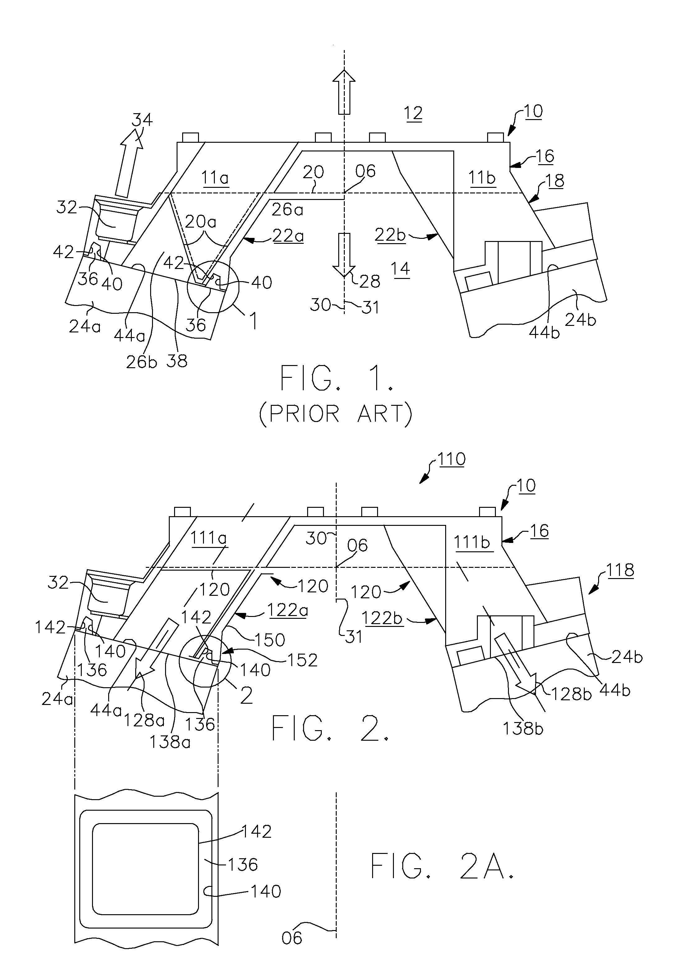
[0015]An improved apparatus and method in accordance with the invention for forming an injection-molded lower intake manifold can be better appreciated by first considering a prior art apparatus and method.

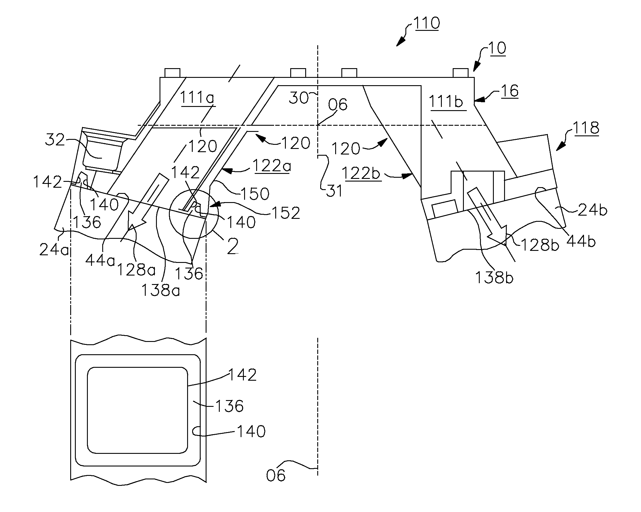
[0016]Referring to FIG. 1, a prior art lower intake manifold 10 is formed for joining to an upper intake manifold 12 for a V-style internal combustion engine 14. Longitudinal axis 06 of engine 14 runs parallel to the longitudinal axis of rotation of the engine's crank shaft (not shown). Two-piece lower manifold 10 comprises a top shell 16 and a bottom shell 18 joinable along a weld line 20, formed as by vibration welding, and having left and right bottom shell portions 22a,22b for mating with left and right engine heads 24a,24b, respectively. Lower manifold 10 includes a plurality of runners 11a,11b for distributing air from upper manifold 12 to individual ports (not shown) in cylinder heads 24a,24b, respectively. Note that FIG. 1 shows a cross-sectional view for left portion 22a ...


PUM

PropertyMeasurementUnit
lengthaaaaaaaaaa
angleaaaaaaaaaa
symmetryaaaaaaaaaa

Abstract

A lower manifold for a V-style internal combustion engine comprising at least three shells: a top shell for mating with an upper manifold; a left shell for mating with a left engine head; and a right shell for mating with a right engine head. The three shells are formed independently by injection molding and are joined as by vibration welding when aligned in a welding jig. The molds for the left and right shells are formed such that the seal ring groove has a rectangular cross-section having sidewalls perpendicular to the lower shell surface because each left and right shell has its own draft angle preferably perpendicular to its lower shell surface. The method and apparatus of the invention permits runner cross-sections to be significantly rounded, which improves air flow characteristics of the runners.

Description

TECHNICAL FIELD[0001]The present invention relates to molded polymer intake manifolds for internal combustion engines; more particularly, to a multiple-part injection molded intake manifold; and most particularly, to a three-piece injection molded intake manifold wherein the walls of a seal groove are parallel to each other and are perpendicular to a mating engine head surface, and wherein the parts may be formed and die drafted without the use of auxiliary slides.BACKGROUND OF THE INVENTION[0002]Intake manifolds formed by injection molding of polymers are well known in the engine arts. A manifold assembly typically comprises an upper manifold, containing the air entry and control apparatus and an air plenum, and a lower manifold, containing individual runners for supplying air distributed from the upper manifold to the individual intake valve ports in the engine head. The upper and lower manifolds typically are formed separately and are joined as by vibration welding prior to being...

Claims


Application Information

Patent Timeline
Patent Type & Authority Patents(United States)
IPC IPC(8): B21D51/16F02M35/10
CPCF02M35/1036F02M35/116F02M35/10321F02M35/10078F02M35/10216Y10T29/49398
Inventor PEFFLEY, THOMAS R.CONFER, KEITH A.BENSON, DEBRA L.
Owner DELPHI TECH INC
Why Eureka
Try Eureka